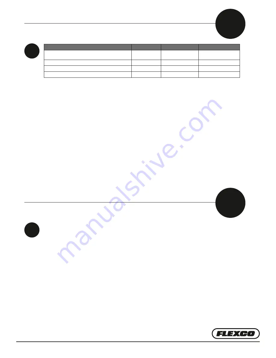
Novitool Aero 1225 Removal Instructions Download Page 17

—17—

B

B1

Inspection Items

Inspection Task

Every Cycle

Every 100 Cycles

Every 1000 Cycles

Inspect press connector bolt condition and replace if condition is 

degraded.

X

Inspect platen condition and clean (G2) or replace as needed.

X

Inspect extrusion and head plates for any signs of fatigue.

X

Inspect power connector pins for signs of arcing or wear.

X

To clean the top and bottom platens, place an all-purpose cleaner on a clean cloth and wipe platens. 

For area requiring further cleaning use a nylon abrasive pad.

C

C1

How to Clean the Platens

Summary of Contents for Aero 1225

Page 1: ...This manual contains important information about product function and safety Please read and understand this manual BEFORE operating the tool Please keep this manual available for other users and own...

Page 2: ...te Removal to Access Electrical Tray 8 Electrical Tray Contents Top Beam Aero 625 and 1525 Electrical Tray Contents 10 Bottom Beam Aero 625 and 1525 Electrical Tray Contents 11 Reassembly of End Plate...

Page 3: ...if it comes in contact with fluids such as water Service shall only be performed by a qualified electrician Power shall be removed before service Follow Lock Out Tag Out procedures Observe proper mai...

Page 4: ...es and adhere to other safety standards of the facility where operating the press Stay alert watch what you are doing and use common sense when operating a machine Do not use machine while tired or un...

Page 5: ...al tray with all electrical and pneumatic components Prior to accessing electrical trays unplug all power cables power switch alone is not sufficient Procedure to remove electrical trays are as follow...

Page 6: ...ulling three connectors straight out inside top beam of press NOTE pull on connectors not wires themselves A Heater connector gray 2 white wires and 1 red wire B Thermal fuse connector gray white wire...

Page 7: ...the 2 pneumatic connections Hold down blue ring of connector and pull hose out 5 Using 6 mm hex key unscrew 3 screws located on front end plate Ensure wires are free to move and not tangled Then gent...

Page 8: ...t electrical connectors Using a 6 mm hex key unscrew 4 screws located on rear bottom end plate Pull away from extrusion 2 Disconnect ground wires from end plate Remove end plate 3 Disconnect by pullin...

Page 9: ...gray white wire C Thermocouple connector yellow 2 mm hex key may be used to assist in removal 4 Using 6 mm hex key unscrew 4 screws located on front end plate Ensure wires are free to move and not ta...

Page 10: ...nts A Umbilical cable B Main controller with display and control knob C Press release valve D USB connector E Cooling fans F Compressor G Thermal fuse relay H Power control PCB I Solid state relay J S...

Page 11: ...connection B Umbilical cable connection C Cooling fans D 24VDC power supply E Thermal fuse relay F Power controller PCB G Solid state relay H S P relay I Buzzer J Fuses Aero 625 Bottom Beam Electrica...

Page 12: ...The tray should slide in with no resistance and the end plate should fit flush to the extrusion If there is resistance check to make sure wires are not catching 2 Using 6 mm hex key screw 3 screws loc...

Page 13: ...onnectors inside top beam of press A Heater connector gray 2 white wires and 1 red wire B Thermal fuse connector gray white wire C Thermocouple connector yellow brown wire Match prongs to same size sl...

Page 14: ...ate flush with the extrusion Place wires within slot at end of extrusion to ensure that the wires aren t pinched between the beam and the head plate If there is resistance a wire may be pinched and mu...

Page 15: ...should fit flush to the extrusion If there is resistance check to make sure wires are not catching Check the bottom of the press to ensure that the air intake perforated plate is not showing 2 Using...

Page 16: ...within the extrusion profile Position head plate flush with the extrusion Place wires within slot at end of extrusion to ensure that the wires aren t pinched between the beam and the head plate If the...

Page 17: ...spect platen condition and clean G2 or replace as needed X Inspect extrusion and head plates for any signs of fatigue X Inspect power connector pins for signs of arcing or wear X To clean the top and...

Page 18: ...LE AERO G3 2135 Spring baffle for 2135 08604 AMIGO FRICTION TAPE 33X25 Tape for clamp bars 09262 BOLT CLAMP TOGGLE AERO G3 Press connector bolt 09342 T C SUBASSY AERO G3 Thermocouple 09343 FUSE ASSY T...

Page 19: ...per RS485 B Lower RS485 B V V V V Main Controller WH GN BN WH GN BN 07 1C 07 1C 07 1C USB USB RD 0 50mm WH 0 50mm 06 3C 06 3C 3x 0 25mm 3x 0 25mm USB Cable 06 8C 06 7C 06 7C FLEXCO 20 15 20 15 Schemat...

Page 20: ...bottom Ground pin 2 Bottom Headplate backside GNYE 2 5 mm LWB supply Splice plate 2 2 1 2 3 4 5 7 7 6 8 9 19 11 10 21 31 40 41 42 05 1A 05 1A 05 1A 05 1A 43 44 33 32 42 9 34 34 L N 110 240 Vac 1a 2a...

Page 21: ...GND 05 1A 05 1A 05 1A B1 WH 0 50mm K 2 A B A B VT 2 5mm BU 2 5mm RD 0 75mm RD 0 50mm RD 0 75mm WH 0 75mm WH 0 50mm OG 0 50mm F4 20Amp F3 20Amp F2 20Amp F1 20Amp F5 4 0Amp TB 1 BN 2 5mm BK 1 5mm BK 2 5...

Page 22: ...ion LWB supply Splice plate 2 2 1 2 3 4 5 7 7 6 8 9 19 11 10 21 31 40 41 42 05 1A 05 1A 05 1A 05 1A 43 44 33 32 42 9 34 34 L N 110 240 Vac 1a 2a 10 8 18 17 16 17 18 16 15 15 13 14 13 14 45 35 12 45 35...

Page 23: ...5mm RD 0 75mm WH 0 75mm WH 0 50mm OG 0 50mm Ground pin 3 Ground pin 4 Pin connections Omron 2 From C DPDT B A 6 5 3 4 2 1 Splice Plate Top Headplate backside E Tray Top m m 5 2 n o l f e T 05 D1 05 D...

Page 24: ...o Extrusion LWB supply Splice plate 2 2 1 2 3 4 5 9 8 6 7 10 1a 2a 110 240 Vac L N 31 40 41 10 10 8 11 12 13 14 15 16 16 17 18 34 34 15 13 14 19 20 7 6 18 17 45 35 45 35 43 44 32 33 9 46 36 2 2 NDR 12...

Page 25: ...Pin connections Omron 2 From C DPDT B A 6 5 3 4 2 1 Splice Plate Top Headplate backside E Tray Top m m 5 2 n o l f e T 08 1D 3 3 4 4 7 8 9 Splice plate 24Vdc 0 Vdc BU 2 5mm 08 1E 08 1E 07 1A 1 2 3 2 3...

Page 26: ...0 BK 1 5mm 10 10 12 14 15 16 15 16 15 16 17 18 17 DKBU 18 VT 19 BU 20 20 19 8 9 9 40 40 57 45 45 46 60 47 61 60 46 OR 0 5mm WH 0 5mm 12 54 55 56 56 56 56 WH 0 75mm RD 0 75 05 1A 59 43 44 24 GNYE 2 5 m...

Page 27: ...DT B A 6 5 3 4 2 1 Splice Plate m m 5 2 n o l f e T Top Headplate backside E Tray Top 4 4 4 4 3 3 08 1C 08 1C BK4 BK3 BK5 BK6 WH 0 75mm RD 0 75mm RD 0 75mm WH 0 75mm 1 1 2 2 2 3 3 3 4 5 6 5 16 16 7 8...

Page 28: ...1 5mm 10 10 12 14 15 16 15 16 15 16 17 18 17 DKBU 18 VT 19 BU 20 20 19 8 9 9 40 42 40 57 45 45 46 60 47 61 60 46 OR 0 5mm WH 0 5mm 12 54 55 56 56 56 56 WH 0 75mm RD 0 75 05 1A 59 43 44 5 22 23 GNYE 2...

Page 29: ...ate m m 5 2 n o l f e T Top Headplate backside E Tray Top 4 4 4 4 3 3 08 1D 08 1D BK4 BK3 BK5 BK6 WH 0 75mm RD 0 75mm RD 0 75mm WH 0 75mm 1 1 2 2 2 3 3 3 4 5 6 5 16 16 7 8 8 7 6 14 16 OG 0 50mm WH 0 5...

Page 30: ...11 13 13 14 15 16 15 16 15 16 17 18 17 DKBU 18 VT 19 BU 20 20 19 8 9 9 40 41 41 40 42 WH 0 75 WH 0 75 42 43 44 59 57 45 45 46 60 47 61 60 46 OR 0 5mm WH 0 5mm 12 54 55 56 56 56 56 58 24 22 23 GNYE 2 5...

Page 31: ...te m m 5 2 n o l f e T Top Headplate backside E Tray Top 4 4 4 4 3 3 08 1D 08 1D BK4 BK3 BK5 BK6 WH 0 75mm BUWH 0 75mm BUWH 0 75mm WH 0 75mm 1 1 2 2 3 3 4 5 6 5 16 16 7 8 8 7 6 14 16 OG 0 50mm WH 0 50...

Page 32: ...enue Downers Grove IL 60515 4200 USA Tel 630 971 0150 Fax 630 971 1180 E mail info flexco com Visit www flexco com for other Flexco locations and products 2020 Flexible Steel Lacing Company 01 20 20 F...

Reviews: