background image

15

 | Replacing the filter liner

Operating manual ALX 73x | file version 00 | 04/2011

C

LEANING

ALX

73x

Replacing the filter liner

The replacement interval for the filter liner must be de-
fined according to the specific circumstances. The fol-
lowing factors determine the frequency:

Dust content of the air

Operating duration

The following error message appears in case of over-
heating:

The filter liner can be cleaned by blowing it out with 
compressed air or by washing it out.

To change the filter liner:

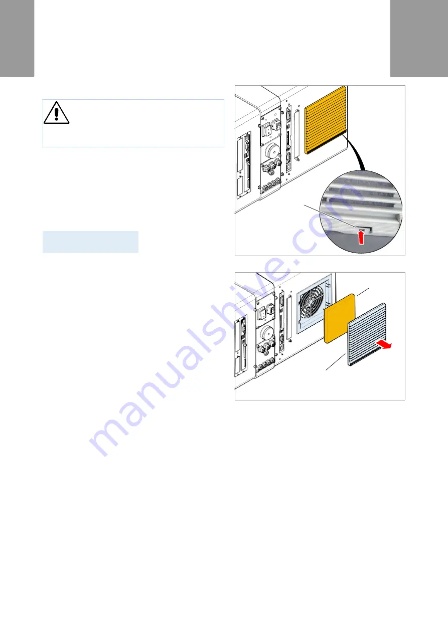
1. Push the locking hook [23A] up with a screwdriver. 

At the same time remove the fan cover [24A].

2. Replace the filter liner [24B] with a new or cleaned 

filter liner (item number: A9752).

3. Press the fan cover in place again.

CAUTION!

A clogged dust filter can result in overheating, 
thereby causing a machine failure.

Replace the filter liner on the fan regularly.

Status num:            5026

MotorProtect CPU

[23] Locking hook (A) on the fan cover.

[24] Remove the fan cover (A).

A

A

B

Summary of Contents for ALX 73 Series

Page 1: ...l cleaning 3 Printhead 4 General notes 4 Cleaning the printhead 5 Replacing printheads 7 Testing the printhead 8 Rubber rollers 9 Feed rollers print roller 9 Pressure roller 10 Deviator rollers 11 Sensors 12 Cleaning the punch sensor 12 Cleaning the material end sensor 13 Cleaning the ribbon path 14 Replacing the filter liner 15 ...

Page 2: ...achine Do not spray the machine with spray bottles or sprays Use a cloth wetted with cleaning agent Repairs to the machine must only be made by trained service technicians CAUTION Sharp cleaning materials may damage the printer Do not use any cleaning agents or materials that could damage or destroy the paint finish labelling display type plates electrical component etc Do not use any scouring cle...

Page 3: ...04 2011 CLEANING ALX 73x General cleaning Dust particles are especially likely to accumulate in the area of the print mechanics Remove dust particles with a soft brush or a vacuum cleaner Clean the housing with a cloth and a standard com mercial neutral cleaner ...

Page 4: ... of irreversible adjustment of the prin thead position Never loosen the screws 1A on the prin thead If a print head ever becomes misaligned remove the entire printhead and send it in to us for realigning Electrostatic discharge or contact with sharp edges can damage the printhead Always protect the printhead against elect rostatic discharge when performing main tenance and cleaning work Never touc...

Page 5: ...Thermal direct print every time the label roll is changed Preparing the printhead 1 Switch off the machine 2 Unplug the mains power connecting line 3 Remove the label material and ribbon 4 Remove both wing bolts 3A until the printhead can be swivelled up Before swivelling the printhead up shift it about 1 cm towards the middle of the axle If the printhead is not at the limit stop on the side mark ...

Page 6: ...rmal strip of the printhead 7 Fasten the printhead in place again 1 After cleaning move the printhead holder back to its former position and retighten the wing bolts The wing bolts must press against the chamfer of the square axle Ensure that the printhead is properly positioned relative to the label edges Factory set printhead position at the limit stop on the inside of the black plastic bushing ...

Page 7: ...ntil the entire print head can be removed from the pressure shaft 6 Install the new printhead at the former position and retighten the wing bolts Factory set printhead position at the limit stop on the inside of the black plastic bushing The wing bolts must press against the chamfer of the square axle Pay close attention to the position of the print head in relation to the edge of the label 7 Plug...

Page 8: ...ssage indicating a faulty dot If all dots are fault free no message appears If an error message occurs the current print job is stopped Duration of the dot check The entire check can last from 10 s to several minutes depending on the printhead the wider the printhead and the more defective dots the longer the duration of the check Interrupting the dot check Press the feed cut online keys To cancel...

Page 9: ...ial has been removed Cleaning the rollers 1 Switch off the machine 2 Remove the mains power connecting line 3 Remove the material and or ribbon 4 Wipe off the rollers with a dust free cloth and roller cleaner Rotate the roller step for step until it is complete ly clean It is also possible to clean the print roller from the front To do this remove the printhead See Replacing printheads on page 7 C...

Page 10: ...ntheads on page 7 8 Wipe off the pressure roller 15A using a lint free cloth and roller cleaner part no 98925 Rotate the roller step for step until it is completely clean 9 Reinstall the guiding section and fasten it with the bolt Push the guiding section with the groove 16A over the rear guide tab on the sensor arm 16B 10 Reinstall the printhead at its former position WARNING Burn hazard The prin...

Page 11: ...1 CLEANING ALX 73x Deviator rollers Glue from the label material may adhere to the deviator rollers Moisten a clean cloth with cleaning solvent and wipe off the dirty deviator rollers 17 with it 17 Rubber rollers dark grey and deviator rollers light grey on the ALX 73x ...

Page 12: ...ide section 18A from side 6 Write down the position of the sensor thumb wheel 18B 7 Turn the thumb wheel all the way to the outside to move the sensor arm 8 Using compressed air blow out the gap 19A in the sensor arm canned air is available as an accesso ry If the sensor is heavily contaminated use cleaning solvent and a lint free cloth to clean the sensor 9 Reinstall the guiding section and faste...

Page 13: ...ial guide The sensor must be cleaned of material and dust residue regularly The cleaning intervals de pend on the material in use Clean the sensor arm using compressed air canned air is available as an accessory If the sensor is heavily contaminated use cleaning solvent and a lint free cloth to clean the sensor 21 Material end sensor A in the inside material guide A ...

Page 14: ...ibbon path All parts which come into contact with the ribbon 22 must be cleaned on a regular basis The following min imum distances apply Once per week or Every 5000 m of ribbon 22 Parts where ribbon residue gathers A Ribbon roller B Deflector roller stress relief C Deflector D Deflector tab on printhead A B C D ...

Page 15: ...ating The filter liner can be cleaned by blowing it out with compressed air or by washing it out To change the filter liner 1 Push the locking hook 23A up with a screwdriver At the same time remove the fan cover 24A 2 Replace the filter liner 24B with a new or cleaned filter liner item number A9752 3 Press the fan cover in place again CAUTION A clogged dust filter can result in overheating thereby...

Reviews: