


SMART-MR15
TM
GM-14915105
Rev 3
Mar/2012
This guide provides the information
required to set up and begin using
your new SMART-MR15, a combined
L1+L2 GNSS receiver and antenna
with an integrated cellular modem with
NTRIP correction support. The
SMART-MR15 also provides
Bluetooth
®
2.0
wireless connectivity
and Emulated Radar (ER) output.
For more detailed information about the installation and
operation of your receiver, refer to the SMART-MR15 and
OEMV
®
user manuals, which can be found on the NovAtel Web
site at:
www.novatel.com/support/firmware-software-and-manuals/
SMART-MR15 BOX CONTENTS
In addition to this quick start guide, the following are provided
with your SMART-MR15:
•
1 - SMART-MR15 cellular activation guide
•
1 - CD containing:
• An installation program for the NovAtel PC Utilities
• Product documentation
•
1 - User Manual postcard for requesting printed manuals
AVAILABLE ACCESSORIES
The following SMART-MR15 interface cables can be ordered as
accessories:
•
Evaluation cable (NovAtel part number 01018515) with
a 23-pin connector on one end and three DB-9
connectors and exposed tinned wires for power, ER,
ground, MKI, MODE, PPS and CAN, on the other. This
cable is designed to allow the rapid deployment and
evaluation of a SMART-MR15 on a construction or
agricultural vehicle. All signals are wired out in this
cable. The Evaluation cable is not intended for
permanent installations.
•
Streamlined cable (NovAtel part number 01018526) with
two DB-9 connectors, and exposed tinned wires for
power, ground and ER. This cable provides connection
for power, two serial ports, and emulated radar. It has
been designed for permanent installation. The cable
material is capable of withstanding a wide temperature
range and is not damaged by exposure to chemicals.
Four mounting kits are available for the SMART-MR15:
•
Mounting Kit, Quick Release Plate (01018625)
•
Mounting Kit, Quick Release Assembly (01018578)
•
Mounting Kit, AG GPS 262 (01018623)
•
Mounting Kit, 5/8 Inch Adapter (01018624)
In addition to the above cable and mounting accessories, the
following accessories are available for the SMART-MR15:
•
CDMA Antenna, 2.2 / 4 dBi, 824-896 MHz / 1850-1990
MHz, NMO [NovAtel part number 12023296] (USE with
12023301 mount only)
•
CDMA Antenna Base, NMO Magnetic Mount, 30 cm
cable [NovAtel part number 12023301] (USE with
12023296 CDMA Antenna. DO NOT USE with
12023303 GSM/GPRS/HSDPA Antenna)
•
GSM/GPRS/HSDPA Antenna, 3 / 4 dBi, 806-960 MHz /
1710-2500 MHz, NMO [NovAtel part number 12023303].
(USE with the 12023300 GSM/GPRS/HSDPA mount
only. DO NOT USE with 12023301 CDMA Base).
•
GSM/GPRS/HSDPA Antenna Base, NMO Magnetic
Mount, 3.65 m cable [NovAtel part number 12023300]
(USE with 12023303 GSM/GPRS/HSDPA Antenna only)
•
Antenna Ground Plane Kit, for use on non-metallic
mounting surfaces [NovAtel part number 01018684]
ADDITIONAL EQUIPMENT REQUIRED
The following additional equipment is required for basic setup:
•
A Windows
®
-based computer with an RS-232 DB-9 port.
•
A battery connection (+9 to +36 V DC)
INSTALLING THE PC UTILITIES
Before setting up your SMART-MR15, install NovAtel’s
PC
Utilities
on the
Windows-based computer that you will use to
communicate with it. This computer must have an RS-232 DB-9
port
.
1. Start up the computer.
2. Insert the accompanying CD into the CD-ROM drive of the
computer.
3. Select
Install the OEMV PC Utilities
from the window that is
automatically displayed. If the window does not
automatically open when the CD is inserted, select
Run
from
the
Start
menu and select the
Browse
button to locate
Setup.exe
on the CD drive.
4. Install the PC Utilities by advancing through the steps
provided in the
NovAtel GPS PC Utilities
setup program.
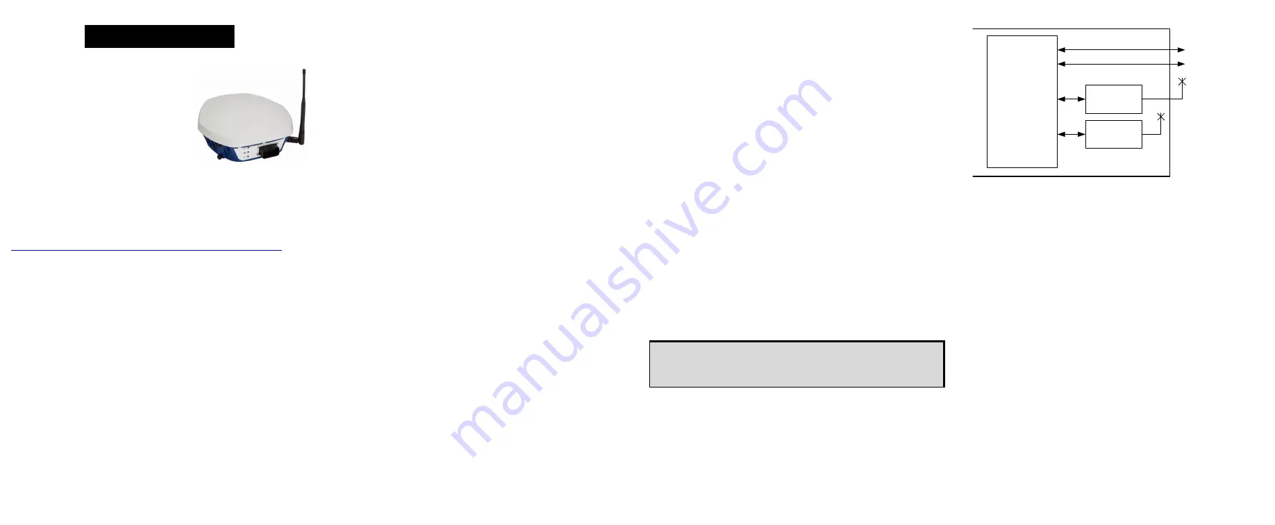
SETTING UP YOUR SMART-MR15
Figure 1: SMART-MR15 System Diagram
The SMART-MR15 system architecture is shown in
. For
the basic setup, you need a Windows-based computer with an
RS-232 DB-9 port and NovAtel PC Utilities installed on it, and a
battery connection (+9 to +36 V DC). Complete the following
steps to connect and power your receiver.
1. Mount the SMART-MR15 on a secure, stable structure with
an unobstructed view of the sky. Mount the cellular antenna
at least 30 cm from the SMART-MR15.
2. Connect the interface cable to the SMART-MR15.
QUICK START GUIDE
To access and download the most current version of our
OEMV PC Utilities, go to the
Support
page of the NovAtel
web site at www.novatel.com.
SMART-MR15
CPU
Bluetooth
Module
DB9 Labeled COM1
COM1
COM2
AUX
COM3
DB9 Labeled AUX
SMART-MR15 Enclosure
Cellular
Module