


CONNECTING TO THE SMART-MR10
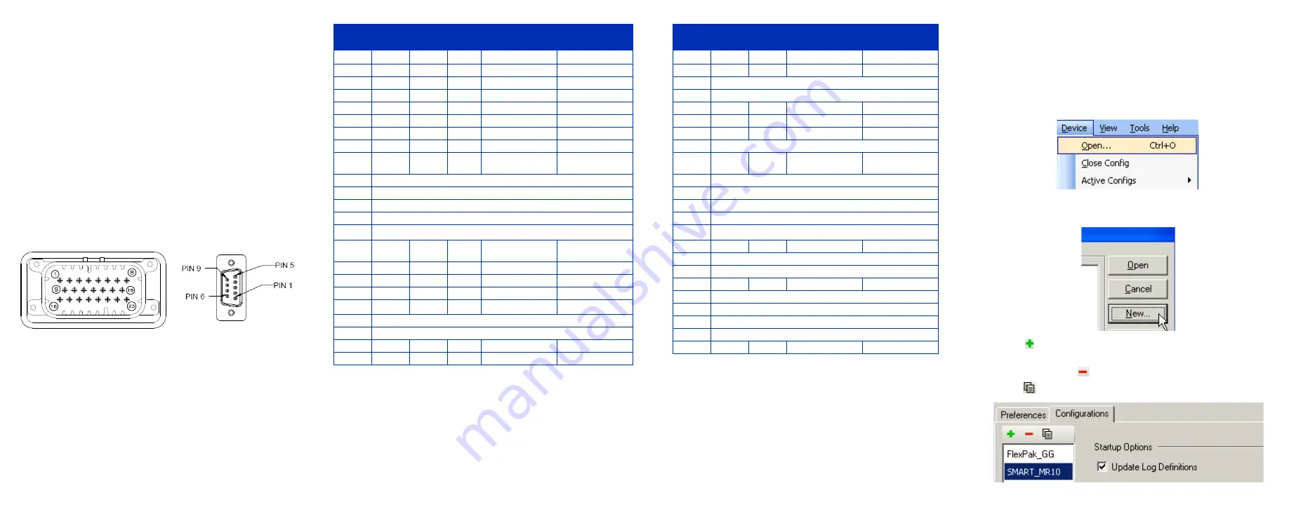
Cable connectors are illustrated in
. One DB-9
connector can be used to connect to a PC/laptop serial (RS-232)
communication port. The others can be connected to a modem
or radio transmitter to receive differential corrections (refer to
your user-supplied modem or radio transmitter information for its
connectors). In addition, there are a number of bare wires where
the outer insulation is cut away at the ends to expose tinned
wires. See
for their pinouts. Cables are
RoHS compliant.
The SMART-MR10 cable provides a means of supplying power
from a battery. The bare power wires (red for positive and black
for negative) are connected to a battery capable of supplying at
least 5 W. A 5 AMP fuse must be installed between the positive
terminal of the battery (or power distribution point) and the
positive supply lead of the cable to protect the wiring from short
circuit damage.
Figure 1: 23-pin and DB-9 Connectors
Table 1: SMART-MR10 Evaluation Cable
Table 2: SMART-MR10 Streamlined Cable
COMMUNICATING WITH THE SMART-MR10
To open a serial port to communicate with the receiver, complete
the following steps.
1.
Launch
CDU
from the
Start
menu folder specified during the
installation process. The default location is
Start |
All Programs | NovAtel PC Software | NovAtel CDU
.
2.
Select
Open....
from the
Device
menu
.
3.
Select the
New...
in the
Open
dialog box. The
Options |
Configuration
dialog opens.
4.
Click
at the top of the configurations selection box to add
a new configuration. To delete a configuration, select it from
the list and click
. To duplicate an existing configuration,
click
. You can select any name in the list and edit it.
TYCO
23-pin
COM1
COM2
AUX
TINNED
LEAD
SIGNAL NAME
1
PWR+ (red)
PWR+
2
PWR- (black)
PWR-
3
CAN- (green)
CAN-
4
CAN+ (yellow)
CAN+
5
2
TXD2
6
3
RXD2
7
2
TXD1
8
2
RTS1/AUXTX
9
SIGGND2
(white/black)
SIGGND2
10
RESERVED
11
RESERVED
12
RESERVED
13
RESERVED
14
CHASSIS GROUND
a
a. Pin 14 of the TYCO 23-pin connector is connected to cable
shields.
15
5
5
5
SIGGND1
(white/ black)
SIGGND1
16
MKI (white)
MKI
17
PPS (orange)
PPS
18
ER (blue)
ER
19
MODE (violet)
MODE
b
b. If the MODE pin is not connected, pins 8 and 22 provide
RS-232 access to the AUX port and COM1 has no flow con-
trol. If the MODE pin is tied LOW, pins 8 and 22 provide
TXD1- and RXD1- for COM1 RS-422, and the AUX port
(RXD3, TXD3) is not available. If the MODE pin is tied
HIGH, pins 8 and 22 provide RTS1 and CTS1 for COM1
flow control, and the AUX port (RXD3, TXD3) is not avail-
able.
20
RESERVED
21
RESERVED
22
3
CTS1/AUXRX
23
3
RXD1
TYCO
23-pin
COM1
COM2
TINNED
LEAD
SIGNAL NAME
1
PWR+ (red)
PWR+
2
PWR- (black)
PWR-
3
RESERVED
4
RESERVED
5
2
TXD2
6
3
RXD2
7
2
TXD1
8
RESERVED
9
SIGGND2
(white/black)
SIGGND2
10
RESERVED
11
RESERVED
12
RESERVED
13
RESERVED
14
CHASSIS GROUND
a
a. Pin 14 of the TYCO 23-pin connector is connected
to cable shields.
15
5
5
SIGGND1
16
RESERVED
17
RESERVED
18
ER (blue)
ER
19
RESERVED
20
RESERVED
21
RESERVED
22
RESERVED
23
3
RXD1
SMARTAG


