NovaLynx Corporation________________________________________________________________________________
200-WS-02
Page 11
April 2021
Lubrication
1.
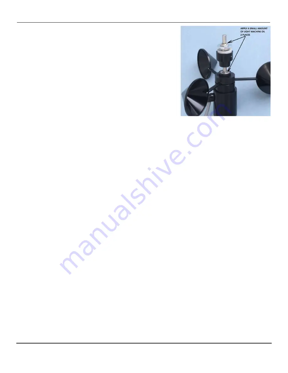
Apply a tiny drop of light machine oil (e.g. fishing reel oil) to
the shaft of the potentiometer where it enters the bearing.
Turn the potentiometer shaft to work the oil into the bearing.
Do not apply too much oil as it could spread inside the
potentiometer and contaminate the resistance material.
2.
Apply a few drops of light machine oil to the top of the ball
bearing that supports the cup assembly. Spin the cup
assembly to work the oil into the bearing.
3.
Wipe excess oil off of the bearing and potentiometer shaft.
Test and Balance
1.
Perform the Anemometer Electrical Test (Section 11.1). The test will confirm that the reed switch
responds to the magnets when the cup assembly rotates.
2.
Perform the Potentiometer Electrical Test (Section 11.2). This test will ensure the electrical output
of the direction sensor is working. The procedure includes information on how to align the vane
with the potentiometer. Install the vane according to the instructions.
3.
The final step is to balance the wind vane. Hold the base of the sensor and turn it sideways so that
the sensor is horizontal to the ground. If the vane is balanced it should show no tendency to rotate.
If it is not balanced either the counterweight or tail will rotate downwards. If the vane is out of
balance, loosen the vane set screw (Figure 1) and slide the vane either forwards or backwards to
balance the vane. Don’t forget to align the tail with the vertical axis while you tighten the set screw.
11
FUNCTIONAL TESTS
The following checks can be done with an ohm-meter after the sensor has been removed from the
tower or tripod. These tests can help determine whether the sensor needs repair or adjustment.
11.1
Anemometer Electrical Test
Set the ohm-meter to a low resistance range and touch its leads together to check for zero ohms. If it is
an analog meter adjust the dial to read zero ohms. Connect the meter to the wind speed output signal
wire and ground wire.
Rotate the cup assembly slowly until you notice the meter reading drop to less than 10 ohms. Continue
to rotate until the switch opens (high resistance). Do this for each of the 3 magnets in the cup
assembly. If the meter always reads a low resistance then the reed switch is not opening (the contacts
may have welded together) or there may be a short circuit in the cable. If the switch never closes then


