


80-9369-0120-020 (09-08)
7
PAS
DN
T2
T1
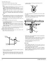
Pinion
Timing Pulley
Screw
ELS Board
Pulley
LED
Timing Belt
Pinion
Timing Pulley
CW
CCW
ELS Board Timing Instructions:
**NOTE: If LED should turn off during the above procedure without
any significant movement of ELS Board Pulley, this is not a problem.
The timing zone range is large enough to allow for slight movement
of ELS Board pulley during tightening of pinion timing screw.
Note: The ELS board is factory-calibrated without any pre-load on
the pinion. When the unit is properly installed, and there is pre-load
on the pinion, the light on the ELS board will not be lit. This is not a
problem. The LED is simply intended to set the ELS Board Pulley in
the appropriate “timing zone”.
Pre-Load Arm per instructions. See page 4.
Re-teach Closed and Open Positions. See page 5.
Place 3 position Selector Mode Switch in the “ON” position for
normal operation.
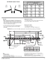
Belt Deflection 1/16” – 1/8”
RH-PUSH UNITS:
Rotate the ELS Board Pulley Counter-Clockwise unit hard stop is
reached.
Slowly rotate ELS Board Pulley Clockwise (away from hard stop
less than 1/8th turn) until the LED on the ELS board lights.
: Pinion pulley should be rotating with the ELS Board Pulley
during this step.
Hold the Pinion Pulley stationary while tightening the pinion
timing pulley screw with a 5/32 hex wrench.**
The ELS board is now calibrated for a RH-PUSH Unit.
Note
•
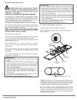
• Depress and hold Black Button on the ELS Board.
While
depressing button, turn power input to unit “ON” and continue
depressing button until the ELS Board LED flashes three (3)
times. The installer then has three (3) seconds to release the
button after the LED flashes.
•
•
•
!
WARNING: Make sure dip switch #3 on ELS Board
is in the
position and the Selector Mode Switch in is
the “OFF” position when preforming ELS Board Timing
Calibration.
( See Page 2)
“A”
READ STEPS COMPLETELY BEFORE PROCEEDING.
The ELS board is calibrated (Timed) to appropriate starting
zone at the factory.
During a normal installation, this procedure is not required.
If for any reason the ELS Board was removed
or the ELS Board Pulley is turned without the pinion turning, it is
likely the ELS board will need to be re-calibrated (timed).
The ELS board may be timed while unit is mounted to the frame and
door.
The unit may also be timed off the frame and door with the
pinion in the at rest position (no pre-load).
Verify Power Input to Unit is “OFF”
Loosen the pinion timing pulley screw with a 5/32 hex wrench so that
the pinion timing pulley is free to rotate independent of pinion.
Maintain tension on timing belt. Belt should be tensioned so that the
belt can deflect 1/16” to 1/8”.
Remove Pre-Load from Arm. Loosen 1/4-20 Screw on Arm Slide
and allow main arm to rotate toward hinge until it is perpendicular
with frame face.
Determine Hand of Door. See hand marking found on unit manifold
(See Page 2). This will determine the proper calibration step to
follow below.
Verify that ELS Dip Switch #3 is in the
Position and Selector
Mode Switch is turned “OFF”.
NOTE:
CLOSED
IF UNIT IS MOUNTED TO FRAME AND DOOR DURING
THESE PROCEDURES, THE DOOR MUST BE IN THE
POSITION DURING“TIMING”OF BOARD.
“ ”
A
LH-PUSH UNITS:
Rotate the ELS Board Pulley Clockwise unit hard stop is reached.
Slowly rotate ELS Board Pulley Counter-Clockwise (away from
hard stop less than 1/8th turn) until the LED on the ELS board
lights.
: Pinion pulley should be rotating with the ELS Board
Pulley during this step.
Hold the Pinion Pulley stationary while tightening the pinion
timing pulley screw with a 5/32 hex wrench.**
The ELS board is now calibrated for a LH-PUSH Unit.
Note
•
• Depress and hold Black Button on the ELS Board.
While
depressing button, turn power input to unit “ON” and continue
depressing button until the ELS Board LED flashes three (3)
times. The installer then has three (3) seconds to release the
button after the LED flashes.
•
•
•


