background image

Northstar

 Explorer 435/438 

Installation and Operation Manual

28

This troubleshooting guide is written with the 
assumption that the user has read and understood 
the relevant sections in this manual.

It is possible in many cases to solve difficulties 
without having to send the display unit back to 
the manufacturer for repair. Please follow this 
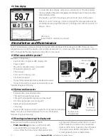
troubleshooting section before contacting the 
nearest Northstar dealer.

There are no user serviceable parts. Specialized 
methods and testing equipment are required 
to ensure that the display unit is reassembled 
correctly and is waterproof. Users who service the 
product themselves will void the warranty.

Repairs to the product may only be carried out 
by a service centre approved by Northstar. If the 
product must be sent into a service centre for 
repair, it is essential to send in the transducer(s) at 
the same time.

More information can be found on our Website: 
www.Northstarnav.com.

1.  The fishfinder won’t turn on:

a)  The Explorer 435 and Explorer 438 are 

designed to operate on a 12 volt battery 
system, where the voltage may vary from 
10 to 16.5 volts. If an excessive voltage is 
supplied, a resettable fuse will be tripped, 
turning the display unit off.

b)  Check that the power cable connector at the 

back of the display unit is securely plugged in 
and the collar is locked in place. The collar must 
be secure for watertight connection.

Appendix B - Troubleshooting

c)  Measure the battery voltage while the battery 

is under load - turn on some lights, radio or 
other electrical equipment connected to the 
battery. If the voltage is less than 10 volts: 

the battery terminals or wiring on the 
terminals may be corroded.

the battery may not be charging correctly or 
may need replacing.

d)  Inspect the power cable from end to end for 

damage such as cuts, breaks, squashed or 
trapped sections.

e)  Ensure that the red wire is connected to the 

positive battery terminal and the black wire to 
the negative battery terminal. If wired for the 
Auto Power option, ensure the yellow wire is 
connected to the ignition circuit. Also check 
the boat’s main switch circuit (see section 6-5 
Wiring options).

f)  Check for corrosion on the power cable 

connector and clean or replace if required.

g)  Check fuses that are placed in line with the 

power cable. A fuse can be blown despite 
appearing to be good or the fuse may be 
corroded. Test the fuse or replace it with a 
fuse known to be good.

2.  The fishfinder won’t turn off:


The fishfinder may have been wired for Auto 
power. In this case, the fishfinder cannot be 
turned off while the ignition power is on. 
(See Auto power wiring in section 6-4 Wiring 
options.)

Explorer 435 and 438

5.0" (126.0 mm)

3.5" (88.5 mm)

1.1" (27.9 mm)

5.7" (143.5 mm)

5.0" (126.0 mm)

Explor

er

 435: 89 

mm (3

.5")

1.2" (30.5 mm)

Explor

er

 438: 97 mm

 (3

.8")

Summary of Contents for EXPLORER 435

Page 1: ...www northstarnav com Explorer 435 438 Fishfinder Installation and Operation Manual ...

Page 2: ......

Page 3: ...orrect the interference by one or more of the following measures Reorient or relocate the receiving antenna Increase the separation between the equipment and receiver Connect the equipment into an output on a circuit different from that to which the receiver is connected Consult the dealer or an experienced technician for help A shielded cable must be used when connecting a peripheral to the seria...

Page 4: ...3 8 Setup Comms Explorer438only 15 3 9 Setup Calibrate 15 4UsingtheExplorer435andExplorer438 16 4 1 Interpreting the display 16 4 2 Fish detection and display 19 4 3 Gain 20 4 4 Range 21 5TheDisplays 21 5 1 Sonar display 22 5 2 Sonar Zoom display 22 5 3 Sonar Bottom display 22 5 4 Sonar A Scope display 23 5 5 Fuel display Explorer438only 23 5 6 Data display 24 6InstallationandMaintenance 24 6 1 Wh...

Page 5: ... sonar depth display can be affected by many factors including the type and location of the transducer and water conditions Ensure that the transducer is located and used correctly Fuel Computer Do not rely on the fuel computer as the sole source of information regarding available fuel onboard Fuel economy can change drastically depending on boat loading and sea conditions Fuel Computer informatio...

Page 6: ...s reefs or wrecks and to help recognize favourite fishing spots from the bottom profile The Northstar fishfinder can also assist with navigation by providing depth information to 1 1BenefitsoftheExplorer435andExplorer438 Important It is vital to the performance of the fishfinder that the transducer is installed in the best location Please follow the installation instructions very carefully help id...

Page 7: ...measuring the time taken between sending a pulse and receiving the echo When an echo has been returned the next pulse is sent The Explorer 435 and Explorer 438 convert each echo into an electronic signal displayed as a vertical line of pixels The most recent echo appears on the extreme right of the display with the older echoes being scrolled towards the left eventually disappearing off the displa...

Page 8: ...der is switched on Use this menu to specify the language see section 3 1 Setup System and units see section 3 7 Setup Units At all other times the title display is followed by the display that was used most recently If the transducer is not connected the message No transducer detected Enter simulate mode will appear Press or to select and press to accept If the transducer was not intentionally dis...

Page 9: ...rol 2 Press to dim or to brighten 3 Press to confirm PowerOff To turn the fishfinder off hold A countdown box appears Continue to hold for 3 seconds until the fishfinder turns off Note If the unit is wired for Auto Power section 6 4 Wiring options the fishfinder can be turned off only when the boat s ignition is turned off SimulateMode An internal simulator allows users to learn how to operate the...

Page 10: ...ow to use the keys in more detail The Setup menu and options are summarized below The factory default settings are shown where applicable Each Setup menu option is explained in the following sections TheSetupmenuandoptions System see section 3 1 Sonar see section 3 2 Simulate see section 2 Comms see section 3 8 Alarms see section 3 6 Data see section 3 4 Logs see section 3 5 Units see section 3 7 ...

Page 11: ...es to 2 hours The fishfinder appears to turn off however all alarms operate normally To return to normal operation press any button Ideal to be used as an anchor alarm Factoryreset This option returns all of the fishfinder settings except the language to the default factory settings shown in section 3 Setting up the Explorer 435 and Explorer 438 Reset to factory defaults appears Press to select Ye...

Page 12: ...ld 5 Press or MENU when finished and the Data header resizes automatically Palette Use this to select a color palette Each color within the palette represents a different echo strength as shown on the sonar displays Thereisachoiceoffivecolor palettes Black Blue White Vivid and 8 color The first four display more detail whilst the 8 color palette shows a greater distinction of signal strength betwe...

Page 13: ...pacity After filling note the reading from the fuel dispenser s gauge Note Beware of air pockets especially in underfloor tanks Tankfull Select Tank full each time the fuel tank s are completely refilled When asked Are you sure select Yes Otherwise the reading on the Fuel display see section 5 5 Fuel Display and the Low Fuel Alarm see section 3 6 Setup Alarms are meaningless Setremaining Before do...

Page 14: ...6Setup Alarms Press MENU twice to display the Setup menu then select Alarms Trigger settings can be defined to suit the boat and individual preferences as follows Alarms can be set enabled to automatically detect certain conditions such as the water being too shallow Alarms that are enabled are shown as black icons in the Alarm status box on the sonar displays When an enabled alarm is triggered th...

Page 15: ...A Specifications and section 5 6 Data display for information about how to display NMEA data Press MENU twice to display the Setup menu then select Calibrate The fuel options can be calibrated only when the optional single or twin engine kit is installed on petrol gasoline engines Speed Calibration may be required because different hull shapes have different flow characteristics Obtain an accurate...

Page 16: ... per engine by refilling the portable tank s to the original level and noting the reading s from the fuel dispenser s gauge 5 Select Fuel Use or to change the reading to match that on the fuel dispenser s gauge 6 Press when the reading is correct Note If the fuel calibration options appear to give erroneous readings after a while first check that the fuel sensor has been installed correctly accord...

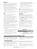
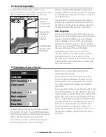
Page 17: ... Setup Sonar If the boat is anchored the echoes all come from the same area of bottom This produces a flat bottom trace on the display The screen shot shows a typical sonar display with the Fish symbols turned Off Size of the fish school of fish or other object Depth of the fish or object Location of the fish or object The area covered by the ultrasonic pulse is a rough cone shape and the echoes a...

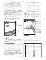
Page 18: ... for an example of the sonar display in such an environment A double bottom trace is shown on the display Sonar display of same area fish is visible on the display fish is hidden by the strong echoes off the bottom and is not shown on the display Example of shadows fish is visible on the display 1 minute ago 30 seconds ago Now When the fish symbol option is on any echo returned that fits the profi...

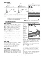
Page 19: ...form a barrier which the fish may not swim through In fresh water fish often collect around a thermocline Fishsymbols The fish symbol can be customized or switched off altogether so that the echoes are not converted to fish symbols on the display See section 3 2 Setup Sonar The differences between Fish symbol On and Off are FishsymbolsOn Using Northstar s SBN sonar technology the fishfinder analys...

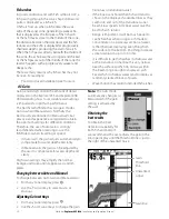
Page 20: ...hickest As the fish passes out of the middle of the cone the reverse happens with a progressively weaker and deeper echo There are many reasons why fish arches may not be seen For example Poor transducer installation see Transom 4 3Gain Gain sensitivity controls the amount of detail displayed on the Explorer 435 and Explorer 438 Understanding how to set suitable Gain settings is important for opti...

Page 21: ...s the area that is magnified Use the or cursor keys to adjust the zoom range Use the or cursor keys to adjust the zoom offset 5 The Displays Press MENU once to show the Display menu then select a particular display using the or cursor keys then press to confirm Section 2 Basic Operation describes how to use the keys in more detail The Display menu is summarized here and each display is shown in th...

Page 22: ... See section 4 4 Range for information about adjusting the Zoom Range and Zoom Offset Zoom bar Sonar history Zoom section Divider line 5 3SonarBottomdisplay To show the Sonar Bottom display highlight Sonar Bottom and press This shows a split display with the sonar history on the right side and the zoom section on the left The bottom signal is shown as a flat trace in the centre of the zoom section...

Page 23: ...n that particular echo is seen at future times on the fishfinder it is likely to be the same fish species Divider line between sonar history and A Scope Gain setting strongest echo for display Gain threshold weakest echo for display To show the Fuel display select Fueland press See section 3 3 Setup Fuel for information about setting up the fuel values If the number of engines is set to 0 the fuel...

Page 24: ...ounting bracket screws included Warranty registration card This manual Sun cover for display unit Flush mounting kit Transom transducer includes cable kit and screws Transom Mount Transducer Installation Manual denotes Explorer 438 only Explorer 500 series chartplotters Through hull depth transducer Through hull speed temperature transducer Fuel flow kit single or twin engine Replacement paddle wh...

Page 25: ...he display unit ensure that the plugs left in the boat are not exposed to the elements Push the attached dust covers over the exposed ends of the plugs Keep the display unit in a dry clean place such as the optional Northstar carry bag 1 Amp fuses must be positioned where shown in the wiring diagrams The power data cable contains 5 wires Wire Function Black Ground power negative White NMEA out Red...

Page 26: ...ower wiring diagram If the external beeper or light requires more than 200 mA total fit a relay Consult your Northstar dealer for more advice Fuelkitwiring Explorer438only See the Fuel Kit Installation Guide for information about the fuel transducer cable Wire the power cable for Auto power as described in this section to make sure the fuel counter starts as soon as the engine starts For twin engi...

Page 27: ...i level backlighting Supply voltage 10 to 16 V DC Supply current at 13 8 V 300 mA min no backlighting 400 mA max full backlighting Output power Variable up to 200 W RMS Operating temperature 32 to 122 F 0 to 50 C Transom transducer cable length Explorer 435 33 ft 10 m Explorer 438 26 ft 8 m Typical depth acquisition time from startup 2 seconds at 100 ft 30 m Receiver sensitivity Better than 10 mic...

Page 28: ...ed in and the collar is locked in place The collar must be secure for watertight connection Appendix B Troubleshooting c Measure the battery voltage while the battery is under load turn on some lights radio or other electrical equipment connected to the battery If the voltage is less than 10 volts the battery terminals or wiring on the terminals may be corroded the battery may not be charging corr...

Page 29: ...tor until the offending device is located To stop problems from electrical noise try re routing the power and transducer cable s away from the boat s other electrical wiring routing the display unit s power cable directly to the battery with an in line fuse 4 Bottom is not displayed a The fishfinder may have Manual Range selected and the depth may be outside the range value selected Either change ...

Page 30: ...el transducer may be clogged If so remove the transducer from the fuel line and gently blow through it in the opposite direction to the fuel flow A fuel filter between the fuel transducer and the fuel tank must be installed as per the fuel installation guide Failure to do so will void the warranty d Inspect the fuel cable from end to end for damage such as cuts breaks trapped or squashed sections ...

Page 31: ......
Page 32: ...y Belvidere Rd Southampton SO14 5QY ENGLAND Ph 44 2380 339922 Fax 44 2380 330345 northstaruk northstarnav com AUSTRALIA PO Box 479 Gladesville NSW 2111 AUSTRALIA Ph 61 2 9879 9060 Fax 61 2 9879 9009 northstaraus northstarnav com NEW ZEALAND PO Box 68 155 Newton Auckland Auckland NEW ZEALAND Ph 64 9 481 0500 Fax 64 9 481 0590 northstarnz northstarnav com www northstarnav com ...

Reviews: