background image

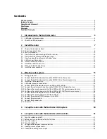
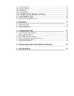
5.4


Calibrating the radar...............................................................................................................................................................33


5.4.1


Prepare for calibration ...........................................................................................................................................................33


5.4.2


Tune the radar...........................................................................................................................................................................33


5.4.3


Set the STC Curve.....................................................................................................................................................................33


5.4.4


Set the trigger delay ...............................................................................................................................................................34


5.4.5


Set the heading calibration (heading sensor installed) ..............................................................................................35


5.4.6


Set the heading calibration (heading sensor not installed) ......................................................................................35


5.5


Adjust the appearance settings ..........................................................................................................................................35


5.6


Restore all the factory settings ............................................................................................................................................36


5.6.1


Restore the factory appearance settings .........................................................................................................................36


6


Maintenance 37


6.1


General maintenance .............................................................................................................................................................37


6.2


Scanner maintenance.............................................................................................................................................................37


6.3


Other maintenance items .....................................................................................................................................................37


7


Troubleshoot the radar 

38


7.1


Technical support, service and repairs .............................................................................................................................38


7.2


Radar is not operating correctly..........................................................................................................................................38


7.3


If the scanner fails to turn......................................................................................................................................................39


7.4


How to reduce noise and interference .............................................................................................................................39


7.5


Make sure the power is present and correctly wired...................................................................................................40


7.6


Confirm the equipment installed .......................................................................................................................................40


7.7


Are Range Rings displayed? .................................................................................................................................................40


8


Manual tuning procedure for the 6000i or 6100i system 

41


9


6 kW Specifications 

42


Summary of Contents for 6 KW RADAR

Page 1: ......

Page 2: ...ice Refer also to the system specifications section Compliance Statement EMC compliance USA FCC Part 15 Class B Refer also to the system specifications section Disclaimer As Northstar is continuously improving this product we retain the right to make changes to the product at any time which may not be reflected in this version of the manual Please contact your nearest Northstar distributor if you ...

Page 3: ...gistration Card In case of any queries refer to www northstarnav com Feedback from you Your feedback is important and helps Northstar ensure that this manual is a valuable resource for all marine technicians E mail your comments or suggestions about this manual to the following address manuals northstarnav com ...

Page 4: ...e radar processor 19 3 4 Install the 6 kW open array 19 3 5 6 kW radar processor connectors 20 3 6 Connect the 6 kW radar processor to a 6000i or 6100i display 21 3 6 1 Connect the radar communications cable NS003107 to the junction box 22 3 6 2 Configure the remote power control for a 6000i or 6100i common power source 24 3 6 3 Configure the remote power control for a 6000i or 6100i different pow...

Page 5: ... 1 Restore the factory appearance settings 36 6 Maintenance 37 6 1 General maintenance 37 6 2 Scanner maintenance 37 6 3 Other maintenance items 37 7 Troubleshoot the radar 38 7 1 Technical support service and repairs 38 7 2 Radar is not operating correctly 38 7 3 If the scanner fails to turn 39 7 4 How to reduce noise and interference 39 7 5 Make sure the power is present and correctly wired 40 7...

Page 6: ......

Page 7: ... not avoided may result in property damage Ensure that mains power is OFF before starting installation or servicing work Electrical shock fire or injury can result if electrical power remains ON or is switched ON during installation or servicing work A potentially lethal high voltage is present and can remain for a period of time after the equipment is turned OFF Ensure that capacitors are dischar...

Page 8: ...ility of anyone being struck or injured by it Never look directly into the scanner at close range while the radar is operating Radar scanners emit electromagnetic energy at a frequency that can be harmful at close range Always keep the recommended safe distance from the scanner as follows Scanner Model Vertical beam angle of scanner degrees Minimum safe distance 100 Watts per m average power densi...

Page 9: ...pply 12 V DC or 24 V DC systems and C is the Network Linker NS004721 The interconnection cable NS003104 contains separate motor power wires and there is a separate motor power fuse in the radar processor If the radar processor is connected to a Northstar 6000i or 6100i it communicates with the display unit through the 6000i and 6100i radar communications cable NS003107 An optional extension cable ...

Page 10: ...unications cable can be added between the radar processor and the 6000i This extension cable is not supplied as standard and must be ordered separately If you re connecting the radar to a Northstar 8000i system you need the 8000i network cable NS00481X which is available is several lengths This is not supplied as standard and must be ordered separately Unpack the boxes carefully and check the cont...

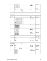
Page 11: ...82 1 This manual MN000357A 1 Installation template LA000281A 1 Product Registration Card CD000085A 1 Spare 5 A fuse Part of hardware kit HR000068 1 Spare 7 5 A fuse Part of hardware kit HR000068 4 Mounting screw HR000061 NS004792R 6 kW radar open array standard components Quantity Item Part name Part number 1 Open array NS004792 1 Assembly instruction sheet LA000277A Northstar 6 kW Radar Installat...

Page 12: ...h 6 5 ft 2 m NS004812 length 16 4 ft 5 m NS004813 length 32 8 ft 10 m NS003107 cable for 6000i and 6100i installations only supplied with 6000i and 6100i system Quantity Item Part name Part number 1 Radar communications cable for 6000i and 6100i installations ONLY NS003107 NS003108 Optional extension cable for 6000i and 6100i installations only order separately Quantity Item Part name Part no 1 Ne...

Page 13: ...ce before you install the radar 2 1 Choose the scanner location The radar s ability to detect targets depends greatly on the position of its scanner The ideal location for the scanner is high above the vessel s keel line where there aren t any obstacles The higher the installation position the longer the radar ranging distance but the minimum range that the radar can detect targets increases the h...

Page 14: ...false echoes and or shadow zones DON T install the scanner where it will be subjected to strong vibrations such as a derrick post because these vibrations will degrade the performance of the radar DON T install an open array close to halyards or flags because the wind could wrap these around the scanner and jam it DON T install the scanner inside of the recommended compass safe distances of any na...

Page 15: ...ll produce an almost horizontal sweep when the power boat is running at speed 2 1 2 Yacht installations Normally you should install the scanner horizontally to produce an equal sweep around the yacht However a yacht heels over to the lee side and when the heel angle exceeds 50 of the vertical beam width of the radar this can cause two problems on the windward side of the yacht the beam is projecte...

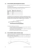
Page 16: ...o high above the A B line the beam will miss close targets and increase sea clutter return You can find the A B line for any vessel as follows 1 Using a drawing of the vessel lay a rule along the line of the main deck and continue this forwards as a dashed line extending beyond the bow 2 Using a protractor measure the θ value for your scanner model below the dashed line at the bow and draw in a ne...

Page 17: ...es and shadow zones False echoes can be produced on the radar display if the scanner is installed too close to an object on the vessel s superstructure This object can block the radar beam and reflect it back generating the false echoes and shadow zones If you re having problems with false echoes and or shadow zones check if it s possible to re install the scanner at a higher location where the ra...

Page 18: ...and rear of the radome The scanner dimensions are shown here Remember that the open array needs a 1320 mm rotation circle Ensure that it will be able to rotate freely and take this diameter into account when calculating the recommended distances from other equipment 12 Northstar 6 kW Radar Installation Manual ...

Page 19: ... from the topside Ensure that you can access the underside of the location site before drilling Tape the paper installation template securely to the chosen location site Before drilling check that the location site is not more than 0 6 15 mm thick to ensure that you can use the bolts supplied you ve oriented the template correctly so that the front of the scanner unit faces the bow and the cable i...

Page 20: ...y rain drips and condensation The location site must allow you to easily connect the radar processor to the ship s ground the interconnection cable the power cable and the 6000i and 6100i radar communications cable or the 8000i network cable Check that these cables and the ship s ground can easily reach the radar processor BEFORE you drill The radar processor dimensions are shown on the drilling t...

Page 21: ...y and secure DO seal and protect all wiring connections if cables are shortened lengthened or re terminated DO leave room to easily access install and remove cables 3 2 Connect the 6 kW interconnection cable NS003104 to the scanner 1 Unscrew and then lift up the hinged cover of the scanner 2 Identify the connector ends B C D E and F on the 6 kW interconnection cable NS003104 Connector end F is an ...

Page 22: ...nection cable through the cable entry point into the scanner Ensure that you push through sufficient cable to easily connect to the J connectors on the lid as described in the following step 7 Connect the four interconnection cable connectors to the four J connectors on the lid as shown Connector end B to J302 Connector end C to J202 Connector end D to J201 Connector end E to J209 16 Northstar 6 k...

Page 23: ...8 Tighten the strain relief clamp then connect Connector end F to one of the screws close by to provide an Earth Northstar 6 kW Radar Installation Manual 17 ...

Page 24: ...ds B C D E and F are shown Pin Color AWG size B C D E F 1 Blue Gray big 16 1 2 Purple Brown big 16 1 3 Red Green big 16 2 4 Yellow Pink big 16 2 5 Drain wire coax line 24 2 6 No connection 7 No connection 8 No connection 9 Yellow thin 24 twist pair 3 10 Axis line 24 1 11 No connection 12 Green thin 24 5 13 White thin 24 twist pair 4 14 Drain wire 24 2 15 Shield line 24 1 16 Orange medium 18 3 Shel...

Page 25: ...o connection 8 Not used No connection 9 RS 485 Comm Yellow thin 24 twist pair 10 Video Axis line 24 11 Not used No connection 12 Bearing Zero Green thin 24 13 RS 485 Comm White thin 24 twist pair 14 Trigger Ground Drain wire 24 15 Trigger Shield line 24 16 Bearing Pulse Orange medium 18 Shell Braid shield 3 4 Install the 6 kW open array IMPORTANT Install the open array onto the scanner ONLY after ...

Page 26: ...d ve Power input Ship s power 12 V or 24 V DC ONLY using the power cable NMEA Comms Data communications for the 6000i and 6100i systems only Remote power control relay and ignition for the 6000i 6100i and 8000i NMEA communications for compass for the 8000i only 6000i or 6100i display unit using radar communications cable NS003107 NS003108 6000i 6100i or 8000i remote power signals relay or ignition...

Page 27: ...the 6 kW radar processor to a 6000i or 6100i display The following diagram shows the recommended method for connecting a radar processor to a 6000i or 6100i display unit Northstar 6 kW Radar Installation Manual 21 ...

Page 28: ...e table shows the wiring and pin details of the radar communications cable The naming convention for the bi colored wires is primary color stripe for example White Orange refers to a white colored wire with an orange stripe If the radar processor is connected through the 12 pin NMEA Comms connector on the radar communications cable NS003107 then all of the NMEA 2 free end signals and grounds must ...

Page 29: ...ite 2 Brown White 2 Red NMEA 2 IN GROUND White 5 White NMEA 2 OUT A Yellow 15 Yellow 7 Orange NMEA 2 OUT B Orange 11 Orange 8 Blue NMEA 2 OUT GROUND Black 10 Black 12 Yellow RS 232 GROUND Tan 17 Tan 1 White RS 232 RX Green 16 Green 3 Green RS 232 TX Red 18 Red 8 Red REMOTE SAVE Orange White 13 Orange White 6000i or 6100i REMOTE POWER OUT Pink 14 Pink SHIELD Drain 9 Drain 9 Drain RADAR REMOTE POWER...

Page 30: ...100i common power source IMPORTANT This remote power control option works correctly only when the 6000i or 6100i and the radar processor share the same power earth and are located 16 5 ft 5 m or less apart A simplified diagram of the power control circuit for the radar processor and 6000i or 6100i is shown 24 Northstar 6 kW Radar Installation Manual ...

Page 31: ...Vbatt to complement the open collector output configuration of the 6000i or 6100i systems There is a choice of two different modes for powering the radar ON OFF If you want the radar to power ON automatically when the radar processor is powered ON connect the White Orange wire to a NMEA ground in the junction box If you want the radar to power ON automatically whenever the 6000i or 6100i is ON pro...

Page 32: ...r to power ON automatically whenever the 6000i or 6100i is ON use the following power ON OFF configuration where Key Component A Radar processor B Main PCB C NMEA Comms port E Relay with normally closed contact F Fuse G NMEA port H Power port I Fuse Breaker board J and K Battery If you want the radar to power ON automatically when the radar processor is powered ON omit the relay and leave Pin 10 a...

Page 33: ...nfigure the remote power control for an 8000i NOTE At the time of printing this manual the 8000i does not support remote power control of network modules This feature will be added in future release The radar processor supports this feature through Pin 12 on the NMEA Comms port If you want the radar processor to power ON automatically whenever power is applied leave Pin 10 and Pin 12 of the NMEA C...

Page 34: ...iant and configured as follows 10 Hz update rate 4800 baud The compass must be able to supply the NMEA 0183 HDT HDM and HTG heading sentences all other sentence types will be ignored Ideally the compass should draw less than 100 mA If this is not possible power the compass using a separate 12 V source 3 8 Connect the power cable The power cable to the radar processor is NOT supplied for either the...

Page 35: ...nstalling the radar processor on a vessel with a metal hull connect the radar processor Chassis Earth to the hull at the closest possible location using 12 AWG wire or thicker The eyelets must be crimped or soldered at both locations A and the method of connection to the vessel s hull is shown at B If you are installing the radar processor on a vessel with a non metallic hull connect the radar pro...

Page 36: ... with the Northstar 8000i system Setting up the radar with the Northstar 8000i is described in the Northstar 8000i System installation documentation for your display processor 30 Northstar 6 kW Radar Installation Manual ...

Page 37: ... active Press it or use the keypad or cursor controls to adjust the value any button displayed in blue is inactive Press it once to activate it The radar normally provides a good picture when used in its automatic modes described in Configuring the navigator In many cases the picture can be improved by using the Range Rider mode Before turning ON the radar for the first time to set it up check tha...

Page 38: ...rthstar 6000i and 6100i accepts the following standard NMEA 0183 sentences from a heading sensor such as the Northstar HS02 or HS03 Heading Sensor to obtain the following heading information HDG HDT OSD HCC HCD and HDM For sensor installation and calibration instructions see the sensor manufacturer s Installation Manual In addition the navigator must be calibrated to the heading sensor see the sec...

Page 39: ...adar uses a fully automatic tuning procedure that continuously checks for optimum adjustment during operation Northstar recommends using auto tuning mode for normal operation For special situations requiring manual tuning see the section on Manual Tuning Mode Tune the radar so that the radar receiver frequency matches the transmitter frequency For normal operation of a Northstar radar you re recom...

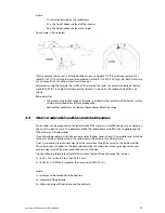
Page 40: ...en press 0 three times to set the sea clutter value to zero 6 Press Gain then press 1 5 0 to set the gain to 150 If you re using standard screen colors the display will show a green ring with a black center or solid green circle If it doesn t try changing the gain value until you can see the green ring and black center clearly If the gain is set too high the display may be saturated 7 Press Page 3...

Page 41: ...ng on the chart and lines up on top of the position shown on the chart 9 If possible check targets in all quadrants to ensure accurate adjustment 5 4 6 Set the heading calibration heading sensor not installed The heading calibration rotates the radar image on the screen so that a target dead ahead corresponds to a bearing of 0 on the screen 1 Press RADAR so that the navigator displays radar only 2...

Page 42: ... the nominal Auto mode setting The value set will be applied only to the current range 5 6 Restore all the factory settings If you need to restore ALL of the radar settings except trigger delay heading calibration and whether or not a heading sensor is installed to their factory settings do the following 1 From the main radar page press Page 1 2 Press Restore 3 Press Restore factory settings to re...

Page 43: ...etic cards because the modulator circuit in the magnetron emits a strong magnetic field that can badly affect such items Remove any dust dirt or sea salt from the external surfaces particularly the front side of the scanner with a lint free cloth dampened with alcohol or water Do NOT use petrol gasoline benzene thinner or similar solvent to dampen the cloth as these cause deterioration of the exte...

Page 44: ... faceplate of the unit When you describe the problem be as complete and as accurate as possible 7 2 Radar is not operating correctly If the scanner is working but no image appears on the display replace the receiver unit see the Service Manual If the display shows only noise check that the tuning is adjusted correctly check the magnetron and replace if necessary see the Service Manual check the mo...

Page 45: ...ty switch 10 Check the wiring of the interconnection cable between the scanner and the radar processor 11 Checking these connections is especially important if the installer removed the connectors for easy routing when installing the scanner cable 7 4 How to reduce noise and interference If other electronic equipment on the vessel is being affected by noise interference from the radar check that t...

Page 46: ... being installed as follows 2 kW 12 V DC Radar Processor NS004780 4 kW 12 or 24 V DC Radar Processor NS004781 6 kW 12 or 24 V DC Radar Processor NS004782 10 kW 24 V DC Radar Processor NS004783 25 kW 24 V DC Radar Processor NS004784 7 7 Are Range Rings displayed Yes range rings are displayed 1 Confirm that the installation set up had been performed 2 Verify that the array is turning If it s a dome ...

Page 47: ... to make it read Manual 5 Press 0 twice on the keypad to set the rain clutter value to zero 6 Press Sea Clutter 7 Press 0 twice on the keypad to set the sea clutter value to zero 8 Press Gain to activate the control 9 If necessary press Gain again to make it read Manual 10 Press 1 5 and 0 on the keypad to set the gain to 150 11 Press Return and Done to return to the main radar screen Next set the ...

Page 48: ... dB width Vertical beam width 20º 20 3 dB width Side lobe level Below 28 dB maximum outside 10º Below 23 dB maximum within 10º Rotation rate Approximately 27 rpm minimum 20 rpm at 70 knot wind maximum Pulse length PRF 0 08µs 30 2250 Hz 5 0 25µs 25 1700 Hz 5 0 5µs 25 1200 Hz 5 1 0µs 25 650 Hz 5 Duplexer Circulator and diode limiter Model NJRC NJS6930 Mixer MIC front end IF amplifier Center frequenc...

Page 49: ...weight 1 9 lbs 870 g Vibration EN60945 Waterproof No rating Temperature range 5ºF to 131ºF 15ºC to 55ºC Relative humidity 95 at 104ºF 40ºC Power up time Approximately 35 seconds DC input 10 8 to 36 V DC 12 24 system Power consumption 3 W when operating Leakage current 200 µA when off with a remote power input Northstar 6 kW Radar Installation Manual 43 ...

Page 50: ......

Page 51: ......

Page 52: ......

Reviews: