


ONL843NW4 11/13
16
Servicing
FUELS - GENERAL
1. Use only clean, high quality fuels of the following
specifications, as defined by ASTM designation
D975 for diesel fuels:
a. Use grade no. 2 diesel at ambient temperatures
above freezing 32°F (0°C).
b. Use grade no. 1 at ambient temperatures below
freezing and for all temperatures at an altitude
of above 5,500 ft. (1500 meters).
2. Use fuel having less than 500 PPM or 15PPM
sulfur (ultra low sulfur fuel).
3. The cetane number should be a minimum of 45.
4. DO NOT use these unsuitable grades of fuel:
a. Domestic heating oils, all types.
b. Class B engine.
c. Class D domestic fuels.
d. Class E, F, G or H industrial or marine fuels.
e. ASTM-D975-60T No. 4-D and higher number
fuels.
5. Storing fuel:
a. Keep dirt, scale, water, and other foreign
matter out of fuel.
b. Avoid storing fuel for long periods of time.
c. Fill the fuel tank at the end of each day’s
operation. This will reduce condensation and
possible biological contamination.
d. If biological contamination is detected or
suspected, contact your dealer for assistance.
6. Biodiesel:
Biodiesel involves the transesterification of vegetable
oils or animal fats. It can involve animal fats, yellow
greases (used greases), cotton seed, sunflower seed,
coconut oil, or sesame seed, but mainly in the US
soybean methyl ester is used (SME). In Europe mainly
rapeseed (canola) methyl ester is made (RME), and in
Asia palm methyl ester (PME) is made. 100% biodiesel
(B100) is made in compliance with ASTM D6751 or
EN14214 (EU) specifications.
Biodiesel may be used in a 5% blend (5% biodiesel/
95% diesel) from a BQ-9000 accredited producer. 20%
biodiesel blends (20% biodiesel/ 80% diesel) can only
be used if they meet ASTM D6751 or EN14214 (EU)
specifications. A 2% reduction in power and a 3%
reduction in fuel economy can be expected if a 20%
blend is used. With a 20% biodiesel blend, an approved
fuel conditioner is recommended. The petroleum part
of the biodiesel blend must meet ASTM D975 or EN590
(EU) specifications. Biodiesel blends must be used within 90
days of their manufacture. When biodiesel blends are used the
oil level must be checked daily and storage, leaking, possible
microbial growth, plugging, and components degradation must
all be checked more frequently.
Note: Using raw pressed or partially refined vegetable oils
or recycled greases as fuel (which have not been through
transesterification) could cause engine failure.
Request a certificate of analysis from an approved biodiesel
fuel distributor to make sure the biodiesel blend meets
specifications.
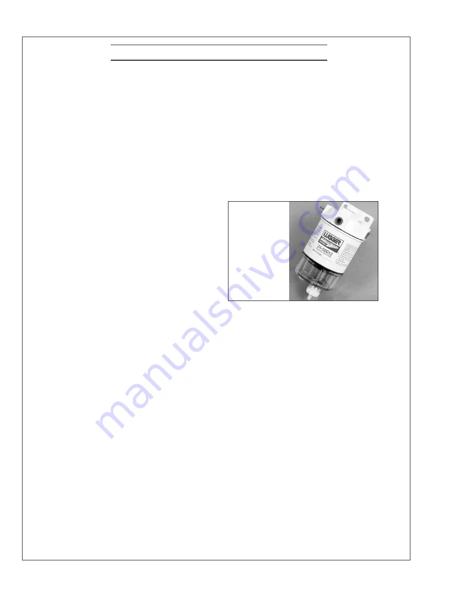
SP7-9. FUEL FILTERS
Figure 8:
Primary Fuel Filter (if provided by Northern
Lights)
1. Your generator set may have a primary fuel filter
installed. We recommend the Racor brand of fuel filter-
water separators.
a. Check the primary fuel filter daily as
recommended by the filter manufacturer.
Empty the collection bowl as necessary.
b. Change the element as often as necessary or
every 500 hours.
c. If the bowl fills with water, change the primary
and secondary element immediately.
2. Change secondary fuel filter every 500 hours.
NOTE: The fuel filter on the engine is considered the
“secondary fuel filter.”
a. Remove the spin-on filter by turning it
counterclockwise with a filter wrench. Fill the
new cartridge with fuel and install it after
applying engine oil to gasket surface. Screw on
until the gasket surface comes into contact with
sealing surface of filter base. Then, tighten it
two-thirds of a turn by hand. Do not overtighten.
b. Secondary fuel filter cartridge part number is:
NL843NW4
–
#24-52020
Primary
Fuel Filter
Part Numbers
Complete Unit:
24-50002
Element:
24-50012


