Northern Lights Lugger ONL753W2 Operator'S Manual Download Page 12

ONL753W2  10/09

12

Servicing

LUBRICATION - GENERAL

1.  Use only clean, high quality lubricants stored in 

clean containers in a protected area.

2.  These lubricants are acceptable: 
 

a.  API Service CC/CD/CE single viscosity oils.


b.  API Service CC/CD/SF multi-viscosity oils.

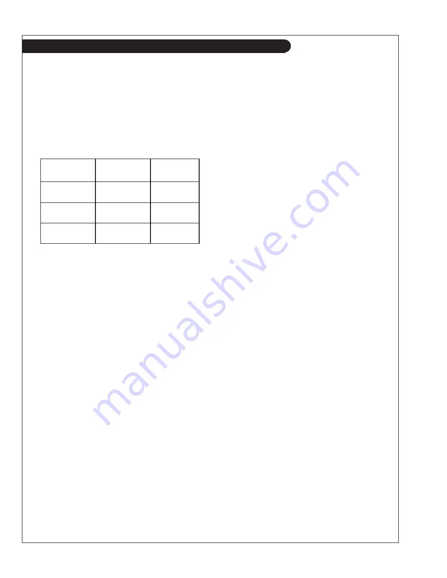
3.  Use the proper weight oil for your average operation 

temperature.

Figure 4:  Lube Oils

4.  Some increase in oil consumption may be expected 

when SAE 5W and SAE 5-20W oils are used. Check 
oil level frequently.

5.  Never put additives or fl ushing oil in crankcase.

SP1.  CHECKING OIL LEVEL

1.  Check the oil level in the crankcase with the dip-

stick. The oil level must be in the waffl ed area 


on the stick. Never allow the level to go below this 
area. Follow the lubrication recommendations above.

SP2.  OIL CHANGES

1.  The set is delivered with special break-in oil. 
 

Change the engine oil and oil fi lter after 50 hours 


of operation. Use Service CC 30 weight oil during 
the fi rst 100 hours.

2.  Change the oil and fi lter again at 100 hours using the 

oil recommended in Figure 4. After this, change oil 
and fi lter every 250 hours.

3.  During intermittent cold weather operation, change 

oil every 100 hours or six weeks, whichever comes 
fi rst.

4.  Change oil at any seasonal change in temperature 

when a new viscosity of oil is required.

5.  Change oil when engine is warm.
6.  Dispose of waste oil in an approved manner.
7.  Never use a fl ushing oil.
8.  Loosen the clamp on the oil change tube. Remove 

cap. Drain oil. Replace the cap and tube.

9. Refi ll engine with recommended oil.
10. Engine capacity with new oil fi lter is:


   3.7 quarts (3.5 liters)

SP3.  CHANGING LUBE OIL FILTER

1.  Change the lube oil fi lter every 250 hours.
2. Use 

fi lter wrench to remove old fi lter. Dispose of 

fi lter in approved manner.

3.  Make sure the gasket from the old fi lter is removed 

and discarded. Clean mount face.

4.  Spread a thin fi lm of engine oil on the rubber gasket 

on the new fi lter and screw it on nipple until gasket 
meets the sealing surface.

5.  Using hands only – no wrench – tighten fi lter
 

one-half turn farther. Overtightening can do 

 damage 

to 

fi lter housing.

6.  Fill engine with recommended oil. Start engine and 

check for leakage. Stop engine, wait 3 minutes, and 
check oil level. Add additional oil if necessary.

7. The 

oil 

fi lter part number is:


   #24-02001

 Air 

Single 

Multi-

 Temperature 

Viscosity 

Viscosity

 Above 

32°F 

SAE 30W 

SAE 15-40W

 (0°C)


-10 to 32°F 

SAE 10W 

SAE 10-30W


(-23 to 0°C)

 Below 

-10°F 

SAE 5W 

SAE 5-20W

 (-23°C)

Summary of Contents for Lugger ONL753W2

Page 1: ...ONL753W2 For Models NL753W and NL753W2 OPERATOR S MANUAL Marine Generators Marine Diesel Engines Land Based Generators...

Page 2: ...other reproductive harm CALIFORNIA Proposition 65 Warning Northern Lights 4420 14th Avenue N W Seattle WA 98107 Tel 206 789 3880 Fax 206 782 5455 Copyright 2009 Northern Lights Inc All rights reserved...

Page 3: ...12 Checking Oil 12 Oil Changes 12 Changing Oil Filter 12 Air Filter 13 V Belts 13 Valve Clearances 13 Fuels General 14 Fuel Filters 14 Bleeding the Fuel System 15 Injector Service 16 17 Injection Pump...

Page 4: ...your unit properly Introduction W NL Northern Lights industrial generator set Model number of engine block Bore Cylinders 75 mm 3 Serial Numbers MODELS INCLUDED This manual covers the operating instru...

Page 5: ...or servicing fuel system Keep your hands feet hair and clothing away from power driven parts Check for any loose electrical connections or faulty wiring Engines should be operated only by knowledgeab...

Page 6: ...7 Starter 1 Junction Box 2 Air Filter 3 Crankcase Vent 4 Lube Oil Fill 5 Coolant Fill 6 Injection Pump 7 Dipstick Figures 2 A and B NL753W 8 Fuel Inlet Return 9 Block Water Drain 10 Oil Filter 11 Fuel...

Page 7: ...ne Control switches must be in the RUN position during preheating Preheat switch must be held in ON position during starting 2 ENGINE CONTROL SWITCH To start the engine hold this switch in the START p...

Page 8: ...below this area Always add the same viscosity of oil as is already in the crankcase 3 Check the fuel tank level and open any fuel valves NOTE The battery switch must always be kept ON while the engin...

Page 9: ...arly and turn off the unit if the temperature rises above 230 F 110 C on Industrial sets Repeat trouble shooting 3 If shutdown is activated and the temperature gauge shows temperature within normal te...

Page 10: ...AILY SP1 Check oil level in engine SP5 Check V belt tension SP7 Check primary fuel filter SP13 Check coolant level SP18 Check electrolyte in batteries AFTER FIRST 50 HOURS SP2 3 Change engine oil and...

Page 11: ...ONL753W2 10 09 11 Service Record Notes...

Page 12: ...r operation change oil every 100 hours or six weeks whichever comes first 4 Change oil at any seasonal change in temperature when a new viscosity of oil is required 5 Change oil when engine is warm 6...

Page 13: ...after the cylinder head bolts have been re tightened Engine should be cold and NOT running 3 Watch the valves while turning the engine over by hand Turn until the inlet valve starts to open and the ex...

Page 14: ...Avoid storing fuel for long periods of time c Fill the fuel tank at the end of each day s operation This will reduce condensation SP7 9 FUEL FILTERS 1 Your generator set should have a primary fuel fil...

Page 15: ...lf bleeding However any system may need manual bleeding when a A new fuel filter is installed b The engine has run out of fuel c The fuel lines injection pump or any other fuel system component has be...

Page 16: ...flare nuts Figure 8 Remove delivery lines Figure 9 Remove return line nuts Figure 10 Remove return line Figure 11 Unscrew injector Figure 12 Remove and replace copper sealing washer Figure 13 Reinstal...

Page 17: ...ill lines Tighten lines at injectors Start engine and check for leaks using a piece of paper or cardboard DO NOT use hand to check for leaks SP12 INJECTION PUMP 1 Since operating conditions may vary c...

Page 18: ...y 2 In very dusty applications clean the radiator with compressed air or steam cleaner every 100 hours Clean in the reverse direction of the airflow GENERATOR ENDS The maintenance and operation recomm...

Page 19: ...SP 18 19 BATTERY CARE 1 Check electrolyte level every 50 hours or once per month Add distilled water to manufacturer s recommended level 2 Batteries cables and cable terminals should be checked and cl...

Page 20: ...plug connection Low battery output Check specific gravity of each battery Check electrolyte level of each battery Defective electrical system Repair or replace ground wire Starter Cranks Slowly Low b...

Page 21: ...eck injection nozzles Uneven compression pressure Check cylinder compression pressure between cylinders Engine Runs Irregularly Below normal engine temperature Remove and check thermostat or Stalls Fr...

Page 22: ...Flush cooling system Defective thermostat Remove and check thermostat Defective temperature gauge Check water temperature with thermometer and replace gauge if necessary Water pump impeller worn broke...

Page 23: ...ring broken Replace governor spring Low Oil Pressure Low oil level Fill crankcase to proper level Improper type of oil Drain and fill crankcase with correct oil Partially plugged oil filter Replace fi...

Page 24: ...ONL753W2 10 09 24 Wiring Diagrams 12 Volt DC Engine Wiring Diagram For Northern Lights NL753W NL753W2 with S1 B control pane l Drawing C 5599 Wiring diagrams are subject to change without notice...

Page 25: ...ONL753W2 10 09 25 AC Engine Wiring Diagram For Northern Lights NL753W2 NL753W Drawing B 8280E Wiring diagrams are subject to change without notice Wiring Diagrams...

Page 26: ...ONL753W2 10 09 26...

Page 27: ...ern lights com 4420 14th Ave NW Seattle WA 98107 Tel 206 789 3880 1 800 762 0165 Fax 206 782 5455 Northern Lights and Lugger are registered trademarks of Northern Lights Inc 2009 All rights reserved L...

Reviews: