background image

OM944T  10/08

11

SHUTDOWNS AND ALARMS

1.  Your unit is fitted with a system to protect it from 

high water temperature or low oil pressure.

  a.  Generator sets have shutdown systems to stop 

    the engine. They have no warning horns.

  b.  Other alarms and shutdowns are available as 

    optional equipment.

NOTE:  If your unit is equipped with optional

      shutdowns and alarms, do not rely on your

      warning or shutdown system to the exclusion

      of careful gauge monitoring. Watching your

      gauges can prevent damage to the unit and

      dangerous power losses.

2.  Do the following when your warning or shutdown 

system is activated:

  a.  Check the temperature gauge. If above 205° F 

    (96° C), shut off the engine immediately.

  b.  Use the Trouble Shooting Guide on page 25 to 

    isolate the cause of the overheat.

CAUTION:  Do not remove the water fill 

cap of an overheated engine. Escaping high 

temperature steam can cause severe burns. Allow 

the engine to cool and then remove the cap slowly 

using protective clothing.

  c.  Make repairs and restart after the temperature 

    gauge registers below 200° F (94° C).

  d.  Watch the temperature gauge regularly and 

    turn off the unit if the temperature rises above 

    205° F (96° C). Repeat troubleshooting.

3.  If shutdown is activated and the temperature gauge 

shows temperature within normal temperature range:

  a.  Check the engine crankcase oil level.

  b.  If the oil level is low, fill with recommended 

    lubricating oil and restart. Watch the oil pressure 

    gauge carefully and shut off the engine if it does 

    not show a normal reading (20-60 PSI) after a 

    few seconds of operation.

  c.  If the oil level is normal, DO NOT restart the 

    engine. Call your dealer for assistance.

Operating Procedures

SPARE PARTS

1.  ADE recommends that you keep the following 

  spare parts on hand for field service. The parts are 

  available from your local Northern Lights dealer. 

Some marine models may already have “On-Board 

Kits,” a handy box that contains the most common 

parts you will need.

  a.  Primary and secondary fuel filter elements

  b.  Oil filters

  c.  Air filter elements

  d.  Alternator belt

  e.  Thermostat and gaskets

  f.  Seawater pump impeller and gaskets

  g.  Glow plugs

   h.  Injector and washer

2.  If your set is operating a long distance from a 

  servicing dealer, add the following:

  a.  Complete set of injectors

  b.  Copper washers for injector change

  c.  Complete set of glow plugs

  d.  Fuel lift pump

Summary of Contents for and M38CR2

Page 1: ...OM944T For Models M944T M38CR2 OPERATOR S MANUAL Marine Generators Marine Diesel Engines Land Based Generators ...

Page 2: ... reproductive harm CALIFORNIA Proposition 65 Warning Northern Lights 4420 14th Avenue N W Seattle WA 98107 Tel 206 789 3880 Fax 206 782 5455 Copyright 2008 Alaska Diesel Electric Inc All rights reserved Northern Lights and the Northern Lights logo are trademarks of Alaska Diesel Electric Inc Printed in U S A PART NO OM944T 10 08 ...

Page 3: ...Y RULES 5 COMPONENT LOCATIONS M944T Generator Set 6 7 CONTROL PANELS Northern Lights Generator Sets 8 OPERATING PROCEDURES Break in Period 9 Before Starting 9 Starting 10 Operating 10 Stopping 10 Shutdowns and Alarms 11 Spare Parts 11 SERVICING SCHEDULE CHART 12 13 SERVICING Lubrication General 14 Checking Oil 14 Oil Changes 14 Changing Oil Filter 15 Air Filter 15 Table of Contents SERVICING Conti...

Page 4: ...oduction M Northern Lights marine generator set Model number of engine block Bore Cylinders 94 mm 4 Serial Numbers MODELS INCLUDED This manual covers the operating instructions for M944T M38CR2 marine generator sets which use the 944 engine block Model Numbers Model numbers give the unit s application block model aspiration and RPM Unit Identification Northern Lights marine diesel generator set wi...

Page 5: ...d only by knowledgeable qualified personnel Look completely around engine to make sure that everything is clear before starting Do not operate an engine that isn t in proper working order If an unsafe operating condition is noted tag the set and control panel so others will also know about the problem Provide first aid kits Never leave engine without proper security Turn the coolant tank cap slowl...

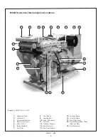
Page 6: ...er Arm Cover 5 Lube Oil Fill 6 Intake Manifold 7 Fuel Filter 8 Air Cleaner 9 Junction Box 10 Lube Oil Dipstick 11 Oil Filter 12 Vibration Mounts 13 Fuel Manifold 14 Fuel Primer Pump 15 Injection Pump 16 Lube Oil Drain 17 Raw Water Pump 18 Heat Exchanger Raw Water Drain and Zinc 19 Heat Exchanger 1 2 3 4 5 6 7 8 9 12 10 13 11 14 15 16 17 18 19 ...

Page 7: ... 10 08 7 M944T Generator Set Component Locations Figure 3 M944T Non Service Side 19 Turbocharger 20 Wet Exhaust Elbow 21 Exhaust Manifold 22 Alternator 23 Belt Guard 24 Starter 25 Oil Pan 19 20 22 23 24 25 21 ...

Page 8: ...tch is used on Series 1 panels only and has a light that glows when the set is running 3 HOUR METER Keeps track of engine running time 4 OIL PRESSURE GAUGE Shows the oil pressure in the engine lubricating system 5 WATER TEMPERATURE GAUGE Registers the temperature of the cooling water 6 D C VOLTMETER When the engine is stopped the voltmeter indicates the condition of the battery When the engine is ...

Page 9: ...sea cock check and clean the sea strainer and reopen the sea cock 5 Place the battery switch in the ON position NOTE The battery switch must always be kept ON while the engine is running If the switch is turned OFF while the engine is running the battery charging alternator could be damaged BREAK IN PERIOD 1 The first 100 hours on a new or reconditioned engine are critical to its life and performa...

Page 10: ...down Bypass switch in the ON position 2 While holding the Shutdown Bypass switch in the ON position push the Engine Control switch to the START position 3 As soon as the engine starts release both switches Do not crank the starter for more than 10 seconds consecutively If the engine fails to start with the first attempt be sure that it has stopped completely before re engaging the starter NOTE Exc...

Page 11: ...he temperature gauge regularly and turn off the unit if the temperature rises above 205 F 96 C Repeat troubleshooting 3 If shutdown is activated and the temperature gauge shows temperature within normal temperature range a Check the engine crankcase oil level b If the oil level is low fill with recommended lubricating oil and restart Watch the oil pressure gauge carefully and shut off the engine i...

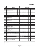
Page 12: ... Inspect starter and alternator Servicing Schedule Chart SERVICE 50 100 250 500 2000 POINT PAGE OPERATION DAILY Hours Hours Hours Hours Hours ENGINE SP1 12 Check oil level SP2 12 Change engine oil1 5 SP3 13 Change lube oil filters1 5 SP4 13 Check air cleaner1 3 4 SP5 13 Check V belt tension1 5 SP7 14 Check valve clearances8 FUEL SYSTEM SP8 15 Check primary filter2 SP9 15 Change primary filter elem...

Page 13: ...ng oil filters SP4 Check air cleaner SP18 Check zinc electrodes EVERY 500 HOURS SP7 Check valve clearances SP8 Change primary filter element SP10 Change secondary fuel filter SP12 Check injectors SP17 Change impeller in seawater pump SP20 Check condition of batteries with hydrometer 1000 HOURS or as required SP13 Check fuel injection pump SP16 Check and clean heat exchanger Service Notes ...

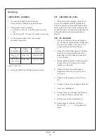
Page 14: ... oil and fill only to the high mark on the dipstick Follow the lubrication recommendations in Figure 5 SP2 OIL CHANGES 1 The set is delivered with special break in oil Change the engine oil and oil filter after 50 hours of operation Use Service CC30 weight oil during the first 100 hours 2 Change the oil and filter again at 100 hours using the oil recommended in the above paragraph After this chang...

Page 15: ... 944T 24 01201 SP4 AIR CLEANER 1 Visually inspect air cleaner every 250 hours In dusty conditions check more often 2 Clean the rubber tube at the cleaner Loosen the hose clamp and the attaching strip for the cleaner 3 Make sure the rubber tube is in good condition and that new filter is absolutely clean and installed properly 4 Start the engine and check for leaks Note Make absolutely sure no impu...

Page 16: ...moment when the two rocker arms are exactly aligned with each other is when they rock Figure 6 Timing Mark 4 Measure the valve clearance for each of the valves with a feeler gauge in the firing order 1 3 4 2 Standard valve clearances for a cold engine are Intake IN 0 0098 in 0 25 mm Exhaust EX 0 0098 in 0 25 mm 5 To adjust valve clearance loosen the lock nut on the adjustment screw Insert a feeler...

Page 17: ...75 60T No 4 D and higher number fuels 6 Storing fuel a Keep dirt scale water and other foreign matter out of fuel b Avoid storing fuel for long periods of time c Fill the fuel tank at the end of each day s operation This will reduce condensation SP8 10 FUEL FILTER 1 Your generator set should have a primary fuel filter installed We recommend the Northern Lights brand of fuel filters a Check the pri...

Page 18: ...t with a cloth to prevent fuel from splashing b Turn the priming pump cap on the fuel feed pump counterclockwise to unlatch it Move the priming pump plunger 2 on Figure 8 up and down To close the pump turn the cap clockwise while depressing it c Close the air vent plug when no more air bubbles can be seen in the fuel flowing from the air vent plug hole Servicing Figure 8 Fuel Feed Pump 3 To bleed ...

Page 19: ... the injector f Remove the injector seat Cover the holes to prevent debris from entering the cylinders Note Do not use pry bars to remove injectors from the cylinder head 3 Injector repair and cleaning a Take injectors to your Northern Lights dealer or local injection repair station for testing and service 4 Injector installation a Install new injector seal washer seat and injector Evenly tighten ...

Page 20: ...rea around the pump with a cleaning solvent or steam cleaner NOTE Never steam clean or pour cold water on an injection pump while the engine is running or the pump is warm b Remove the injection lines from the pump and injectors Remove all lines as an assembly Do not remove the spacers Cover the ends of the lines the injector inlets and the injection pump outlets to keep dirt out of the injectors ...

Page 21: ... 50 maximum solution should be used c The antifreeze should not contain amine silicate or borate SP15 COOLING SYSTEM FLUSHING 1 Flush the cooling system every 2000 hours or every 12 months whichever comes first 2 Remove fill cap and open drains on engine block The engine block drain is on the service side of the engine above the dipstick next to the flywheel housing 3 Pour clean water into the eng...

Page 22: ... the housing 4 Press in the new impeller and place the sealing plug in the outer end of the impeller center if this has not already been done NOTE Make sure that there is always an extra impeller and cover gasket in reserve on board SP18 ZINC ELECTRODES 1 A zinc electrode is installed in the heat exchanger cooling system to protect the engine from electrolysis Check it faithfully every 250 hours I...

Page 23: ...ry BOOSTER BATTERIES CAUTION Battery gas can explode Keep all flames and sparks away from batteries 1 Before changing or using booster batteries check the battery electrolyte level Add distilled water if necessary 2 Booster and main batteries must have the same voltage rating 3 First connect the positive terminal of the booster battery to the positive terminal of the main battery Then connect the ...

Page 24: ... with the mixture Start the engine and operate it with no load for 5 to 10 minutes Stop the engine spray rust preventative agent into intake pipe Drain the rust preventative oil and fuel 2 Drain fresh water and seawater cooling systems completely Flush fresh water systems and refill with the proper antifreeze mixture 3 Drain the water supply lines and wet exhaust line Cover the intake and exhaust ...

Page 25: ...ug connection Low battery condition Check specific gravity of each battery Check electrolyte level of each battery Defective electrical system Repair or replace ground wire Starter Cranks Slowly Low battery condition Battery is too small Battery cables are too small Check specific gravity Replace battery if necessary of each battery Check electrolyte level If low fill cells with distilled water of...

Page 26: ...re Remove and check thermostat or Stalls Frequently Clogged primary Clean or replace filter element fuel filter element Clogged secondary Replace secondary filter element fuel filter element Water or dirt in the fuel system Drain flush fill and bleed system Dirty or faulty injection nozzles Have your dealer check injection nozzles Air in fuel system Inspect clamps and hoses on suction side of fuel...

Page 27: ... your thermostats Check water temperature to see if temperature gauge is working properly Faulty fuel injector Call your dealer Engine overheating See Engine Overheating section High Fuel Consumption Improper type of fuel Use correct fuel for temperature Clogged or dirty air cleaner Service air cleaner Engine overloaded Reduce the electrical load Improper valve clearance See your dealer Injection ...

Page 28: ...our dealer Injection nozzles dirty See your dealer Engine overloaded Reduce the electrical load Injection nozzles dirty See your dealer Injection pump faulty Consult your dealer Engine out of time See your dealer Incorrect valve clearance Consult your dealer Engine Emits Improper fuel Use correct fuel for temperature White Smoke Cold engine Warm up engine to normal operating temperature Defective ...

Page 29: ...OM944T 10 08 29 Northern Lights AC Wiring Diagram DST 100 2FAK Voltage Regulator Drawing B 8280D AC Wiring Diagram ...

Page 30: ...30 OM944T 10 08 DC Wiring Diagram DC Wiring Diagram 12 VDC Standard Ground C 6533 Drawings subject to change without notice ...

Page 31: ...OM944T 10 08 31 DC Wiring Diagram DC Wiring Diagram 24 VDC Standard Ground C 6534 Drawings subject to change without notice ...

Reviews: