


12
Northern Industrial Welder
Operating Instructions and Parts Manual
MIG 130
cuffs, high topped shoes, and an
ANSI approved welding helmet.
5.1. Connect the Ground Clamp to a
scrap piece of the same type of
material which you will be welding. It
should be equal to or greater than the
thickness of the actual work piece,
and free of oil, paint, rust, etc.
5.2. Select a heat setting.
5.3. Hold the torch in one hand,
allowing the nozzle to rest on the
edge of the work piece farthest away
from you, and at an angle similar to
that which will be used when welding.
(See HOLDING THE TORCH if you
are uncertain of the angle at which
you will be welding).
5.4. With your free hand, turn the
Wire Speed Dial to maximum and
continue to hold onto the knob.
5.5. Lower your welding helmet and
pull the trigger on the torch to start an
arc, then begin to drag the torch
toward you while simultaneously
turning the Wire Speed Dial counter-
clockwise.
5.6. LISTEN! As you decrease the
wire speed, the sound that the arc
makes will change from a sputtering
to a high-pitched buzzing sound and
then will begin sputtering again if you
decrease the wire speed too much.
The point on the wire speed
adjustment where the high-pitched
buzzing sound is achieved is the
correct setting. You can use the wire
speed control to slightly increase or
decrease the heat and penetration for
a given heat setting by selecting
higher or lower wire speed settings.
Repeat this tune-in procedure if you
select a new heat setting, a different
diameter wire, or a different type of
welding wire.
6. Welding Techniques
EXPOSURE TO A WELDING ARC
IS EXTREMELY HARMFUL TO THE
EYES AND SKIN! Prolonged
exposure to the welding arc can
cause blindness and burns. Never
strike an arc or begin welding until
you are adequately protected.
Wear flameproof welding gloves, a
heavy long sleeved shirt, trousers
with out cuffs, high topped shoes
and an ANSI approved welding
helmet.
ELECTRIC SHOCK CAN KILL! To
prevent ELECTRIC SHOCK, do not
perform any welding while
standing, kneeling, or lying directly
on the grounded work.
6.1 Moving the torch
Torch travel refers to the movement
of the torch along the weld joint and is
broken into two elements: Direction
and Speed. A solid weld bead
requires that the welding torch be
moved steadily and at the right speed
along the weld joint. Moving the torch
too fast, too slow, or erratically will
prevent proper fusion or create a
lumpy, uneven bead.
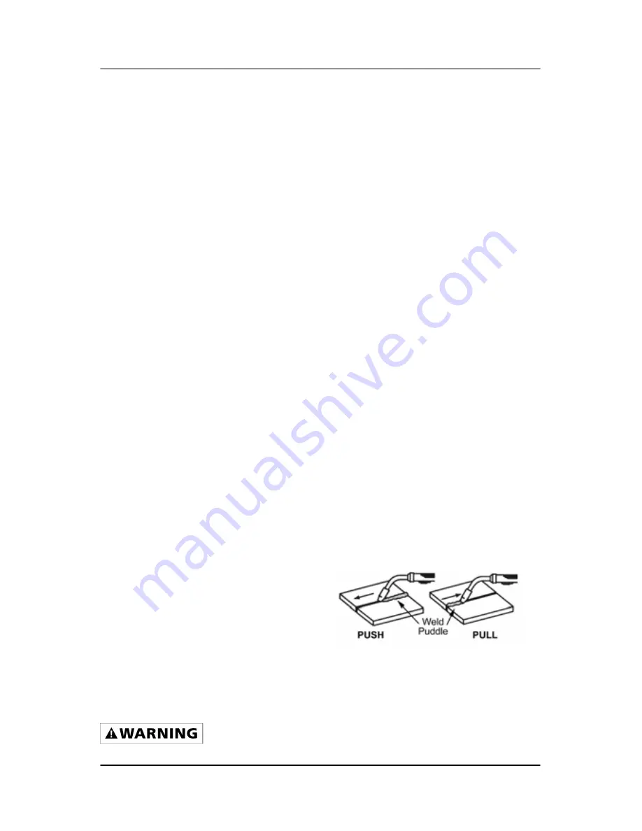
Travel direction
is the direction the
torch is moved along the weld joint in
relation to the weld puddle. The torch
is either PUSHED into the weld
puddle or PULLED away from the
weld puddle.
For most welding jobs you will pull the
torch along the weld joint to take
advantage of the greater weld puddle
visibility.
Travel speed
is the rate at which the
torch is being pushed or pulled along
the weld joint. For a fixed heat setting,


