


4
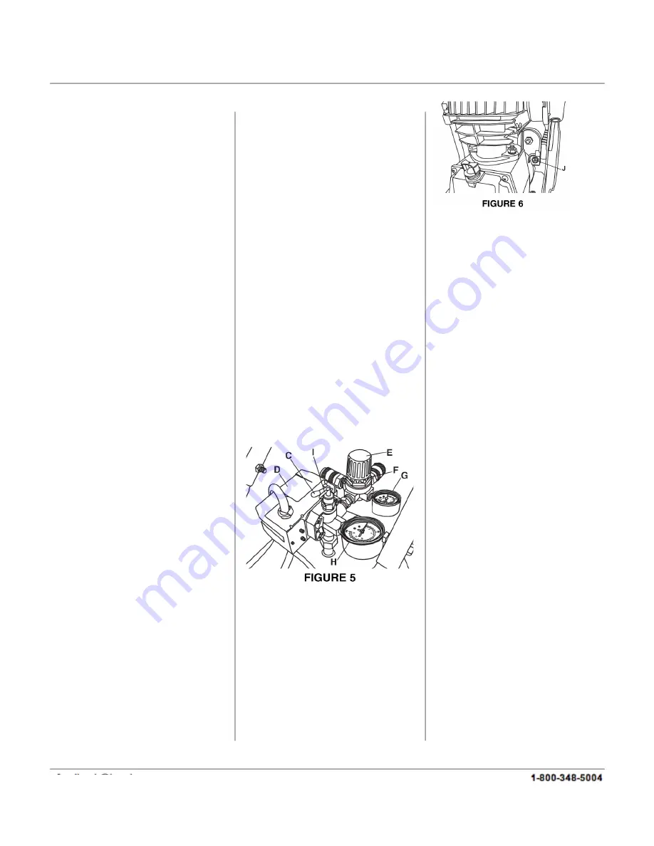
PRESSURE SWITCH (D) FIG.5
The pressure switch automatically
starts the motor when the tank
pressure drops below the factory
set ‘cut-in’ pressure. It also stops
the motor when the air tank
pressure reaches the factory set
‘cut-out’ or maximum pressure.
REGULATOR (E & F) FIG.5
The air pressure coming from the
air tank is controlled by the
regulator (E). To unlock the
regulator, turn the regulator lock
rink (F) counterclockwise and then
turn the regulator clockwise to
increase pressure and
counterclockwise to decrease
pressure, tighten the regulator
lock rink to relock it into position.
To avoid minor readjustment after
making a change in the pressure
setting, always approach the
desired pressure from a lower
pressure. When reducing from a
higher to a lower setting, first
reduce the pressure less than that
desired, then bring it up to the
desired pressure. Depending on
the air requirements of each
particular accessory, the outlet
regulated air pressure may have
to be adjusted while operating the
accessory. This process may
require expelling air from the air
outlet, hose, tool, or accessory.
OUTLET PRESSURE GAUGE(G)
FIG.5
The outlet pressure gauge
indicates the air pressure
available at the outlet side of the
regulator. The pressure is
controlled by the regulator and is
always less than or equal to the
tank pressure.
TANK PRESSURE GAUGE (H)
FIG. 5.
The tank
pressure gauge indicates the air
pressure in the tank.
SAFETY VALVE (I) FIG. 5.
If the
pressure switch does not shut off
the air compressor at its cutout
pressure setting, this safety valve
will protect against high pressure
by popping out at its factory set
pressure (slightly higher than the
pressure switch cut-out setting).
WARNING!
: If the safety valve
does not work properly, over
pressurization may occur,
causing air tank rupture or an
explosion. Daily pull the ring on
the safety valve to make sure
that the safety valve operates
freely. If the valve is stuck or
does not operate smoothly, it
must be replaced with the same
type of valve.
MOTOR THERMAL
OVERLOAD PROTECTOR
(RESET (J) FIG. 6).
The electric
motor has an automatic thermal
overload protector. If the motor
overheats for any reason, the
thermal overload protector will
shut off the motor. The motor
must be allowed to cool before
restarting. Press the reset button
(J) after 15 minutes.
ASSEMBLY AND LOCATION
OF THE AIR COMPRESSOR
Your compressor requires some
assembly. Install intake filter (A)
Fig.7 to the cylinder cover.
Remove plastic cap and install
the oil breather cap (B) to the
crankcase cover. Install both
wheels (C) using the large hex.
bolts, spring washers and hex.
nuts supplied. Then install the 2
rubber feet (D) using the small
hex. bolts, washers, spring
washers and hex. nuts. Install
handle (E) and the storage
compartment (not shown) to the
tank using hex. bolts, washers,
spring washers and hex. nuts.
where applicable.
Operate the air compressor in a
cool, dry, clean and well
ventilated area. The air
compressor pump and case are
designed to allow for proper
cooling. Clean or blow off dust or
dirt that collects on the air
compressor. A clean air
Summary of Contents for 42801
Page 9: ...feedback natitools com 89042801 ...
Page 10: ...feedback natitools com ...


