70
Configuring ISDN BRI hardware
power at -48 V (-40 V for Europe), simplexed over the transmit and
receive pairs. The transmit pair is negative with respect to the receive
pair.
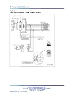
Figure 25
UILC port designation label at the cross-connect terminal
Note: The cable pair designated T R is a 2B1Q full-duplex U interface.
Cross-connecting the DSLs
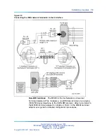
Each SILC provides eight four-wire,
full-duplex ports. These ports connect to building wiring facilities to form
DSLs. Since the DSLs are polarity-sensitive, maintain signal polarity along
each loop as shown in
Figure 26 "Cross-connecting a SILC port to the office
wiring" (page 73)
on
Figure 26 "Cross-connecting a SILC port to the office
wiring" (page 73)
.
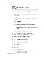
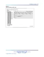
Each UILC provides eight two-wire full-duplex ports. These ports connect
to twisted pair building wiring facilities to form DSLs as shown in
Figure 27
"Cross-connecting a UILC port to the office wiring" (page 74)
on
Figure 27
"Cross-connecting a UILC port to the office wiring" (page 74)
. The DSLs
are not polarity-sensitive, and it is not necessary to maintain signal polarity
along each loop.
Procedure 21
Cross-connecting the DSLs at the cross-connect terminal
Step
Action
To cross-connect SILC and/or UILC ports to the building wiring:
1
Identify the card type (SILC or UILC) at the cross-connect terminal.
2
Identify the transmit and receive connections for the SILC and
the TIP and RING connections for the UILC from the label of the
distribution strip.
Refer to
Table 19 "M5317TDX terminal error codes" (page 81)
to
identify ports and their connections for a SILC or UILC.
3
Identify building wires connected at the cross-connect terminal.
4
Cross-connect the pins from the SILC or UILC to the building wiring.
5
Repeat this procedure for each DSL.
—End—
Nortel Communication Server 1000
ISDN Basic Rate Interface Installation and Commissioning
NN43001-318
01.02
Standard
Release 5.0
20 June 2007
Copyright © 2003-2007, Nortel Networks
.
Summary of Contents for 1000 Con?guration guide
Page 107: ......


