


11
installation manual for the proper type and quantity of
refrigerant.
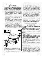
Refrigerant Charging
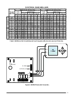
The system refrigerant charge can be checked and
adjusted through the service ports provided at the front
panel of the outdoor unit. Use only gauge lines which have
a Schrader depression device present to actuate the valve.
Air Circulation
Running the Blower Continuously
Set the thermostat’s system mode to
OFF
and the
thermostat’s fan mode to any speed level. The blower
motor should run continuously. Check for air delivery at
the register(s). Ensure that there are no obstructions at
the registers or in the ducts.
NOTE:
If blower is turning opposite of arrow direction, shut
off main power to the unit and switch any two field wires
at the disconnect.
DO NOT
alter unit wiring.
Turning the Blower Off
Set thermostat’s fan mode to
AUTO
, the blower will shut
down immediately.
System Cooling
1. Set the thermostat’s system mode to
COOL
and fan
mode to
AUTO
. Lower the thermostat’s temperature
mode below room temperature and observe that the
blower energizes. Check the air being discharged at
the register is cooler than room temperature. Verify
unit refrigerant pressures are in order. Blower should
be turning in direction indicated by arrow.
NOTE:
DO NOT alter unit wiring. Listen for any unusual
noises. Locate the source and correct as needed.
2. Allow the unit to run for several minutes and then set
the thermostat’s temperature above room temperature.
Verify the blower cycles off with the thermostat.
System Heating
1. Set the thermostat’s system mode to
HEAT
and the fan
mode to
AUTO
. Increase the thermostat’s temperature
above room temperature and observe that the blower
energizes. Check the air being discharged at the register
is warmer than room temperature.
2. Allow the unit to run for several minutes and then set
the thermostat’s temperature below room temperature.
Verify the blower cycles off with the thermostat.
Blower Settings
The iQ Drive thermostat controls the blower speed and
timing to satisfy set temperatures. See iQ Drive thermostat
user manual.
Dehumidification
The iQ Drive system may provide some dehumidification
by lowering the airflow to increase the amount of humidity
that is removed from the circulating air during cooling. See
iQ Drive thermostat user manual.
STARTUP & ADjUSTMENTS
WARNING:
The evaporator coil is shipped from the factory
with a nitrogen charge. Use caution when
preparing coils for field connections. If repairs
make it necessary for evacuation and charging,
it should only be attempted by qualified,
trained personnel thoroughly familiar with this
equipment. Some local codes require licensed
installation service personnel to service this
type of equipment. Under no circumstances
should the equipment owner attempt to install
and/or service this equipment. Failure to comply
with this warning could result in equipment
damage, personal injury, or death.
NITROGEN
HEALTH
FLAMMABILITY
REACTIVITY
0 Minimal Hazard
1 Slight Hazard
1
0
0
Before You Start the Unit
Prior to start-up, complete the following inspections:
√
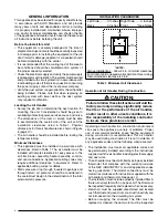
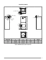
Verify the unit is level and properly located with adequate
clearances for servicing the unit. See Table 1 (page 4).
√
Check condensate drain line(s) for proper drainage.
√
Verify the surrounding area and top of the unit is free
from obstructions and debris.
√
Check all duct connections. Make sure the duct work
is adequately sealed to prevent air leakage.
√
Check all coil connections for leaks.
√
Verify that the line voltage power leads are securely
connected and the unit is properly grounded. Make sure
all doors are installed before restoring power to the unit
√
Verify the thermostat is wired correctly. Make sure all
low voltage wires are securely connected.
√
Verify the power supply branch circuit overcurrent
protection is sized properly.
√
Verify filter is properly and securely installed.
IMPORTANT:
Before starting the unit, install the initial
charge on units that are factory shipped with a nitrogen
holding charge:
1. Read all installation instructions first.
2. Purge the nitrogen holding charge.
3. Evacuate the unit to 350 - 500 microns.
4. Allow the unit to remain under vacuum for at least 30
minutes.
5. Weigh in the proper amount of new (or reclaimed)
refrigerant. Refer to the air conditioner or heat pump


