background image

AIR HANDLER

Please read all information in this manual thoroughly and become familiar with the capabilities 
and use of your appliance before attempting to operate or maintain this unit. These instructions 
are primarily intended to assist qualified individuals experienced in the proper installation 
of this appliance. Installer should be specifically trained to install and setup an iQ system. 
Some local codes require licensed installation / service personnel for this type of equipment. 
Improper installation, service, adjustment, or maintenance may cause explosion, fire, electrical 
shock or other hazardous conditions which may result in personal injury or property damage.

Unless otherwise noted in these instructions, only factory authorized kits or accessories may 
be used with this product. Keep this manual where you have easy access to it in the future. If a 
problem occurs, check the instructions and follow recommendations given. If these suggestions 
don’t eliminate your problem, call your servicing contractor.

DO NOT DESTROY. PLEASE READ CAREFULLY AND 

KEEP IN A SAFE PLACE FOR FUTURE REFERENCE.

IMPORTANT

B6VMAI

INSTALLATION INSTRUCTIONS


Series

Summary of Contents for B6VMAI

Page 1: ...type of equipment Improper installation service adjustment or maintenance may cause explosion fire electrical shock or other hazardous conditions which may result in personal injury or property damage...

Page 2: ...t SAFETY INFORMATION INSTALLER Please read all instructions before servicing this equipment Pay attention to all safety warnings and any other special notes highlighted in the manual Safety markings a...

Page 3: ...operations The information listed below is for reference purposes only and does not necessarily have jurisdiction over local or state codes Always consult with local authorities before installing any...

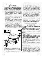
Page 4: ...ons Applicable building codes may require additional clearance to equipment Refer to applicable building codes for details Static pressure drop through louvered openings and through return air plenums...

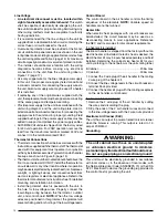
Page 5: ...must be properly insulated to minimize duct losses and prevent condensation Use insulation with an outer vapor barrier Refer to local codes for insulation material requirements Air Filters B6VMAI Ser...

Page 6: ...and floor Upflow Installations All air handlers are factory shipped ready for upflow installation The horizontal drain pan may be removed from the air handler when installing the unit in an upflow con...

Page 7: ...he horizontal drain pan IMPORTANT If the webbing is not removed the condensate will not drain properly and ceiling damage may occur 3 Insert the plug from horizontal drain pan into the open and unused...

Page 8: ...during installation Ifpreciseformingofrefrigerantlinesisrequired acopper tubing bender is recommended Avoid sharp bends and contact of the refrigerant lines with metal surfaces Refrigerant lines shou...

Page 9: ...ng or pvc pipe and adequately trapped Both drain tubes must have a minimum diameter of 3 4 and be trapped separately IMPORTANT Failure to install a trap may resultincondensationoverflowingthedrainpan...

Page 10: ...operation maybeadverselyaffectedbyradiantheatfromfireplaces sunlight or lighting fixtures and convective heat from warm air registers or electrical appliances Refer to the thermostat manufacturer s i...

Page 11: ...SeeiQDrivethermostat user manual Dehumidification The iQ Drive system may provide some dehumidification by lowering the airflow to increase the amount of humidity that is removed from the circulating...

Page 12: ...s on the air handler after servicingorcleaning changingthefilters Donotoperate the air handler without all doors and covers in place Verify that the thermostat is properly installed and is not being a...

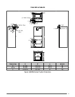
Page 13: ...D B 43 5 16 19 11 16 18 1 4 No Tall B 49 5 16 19 11 16 18 1 4 No C 55 15 16 22 7 16 21 Yes 3 4 3 4 3 4 13 1 1 4 1 5 8 1 7 8 1 1 4 3 1 4 2 5 8 11 8 K O Typ 1 3 4 K O Typ 1 7 8 3 5 8 5 5 8 DETAIL D 3 1...

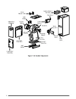
Page 14: ...tor Mount Kit Blower Motor Transformer Capacitor Circuit Breaker 60A Heating Element Assembly Filter Tracks Blower Wheel Blower Housing Control Board Filter Door Upper Door Assembly Lower Door Assembl...

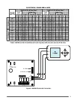
Page 15: ...15 79 1 80 54 1 60 25 0 25 69 0 70 47 4 50 21 6 25 20 104 1 125 54 1 60 50 0 50 90 7 100 47 4 50 43 3 50 25 N A N A N A N A N A N A N A N A N A N A N A N A N A N A N A N A 30 N A N A N A N A N A N A...

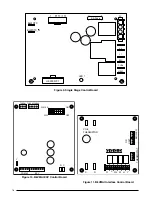
Page 16: ...R W2 W H OD UNIT BLOWER COIL THERMISTOR Figure 10 B6VMAI EXV Control Board R R 410A 1 2 3 4 5 6 7 8 ON OFF R 22 THERM THERM PRESS C Y COMM EXV Figure 11 B6VMAI Interface Control Board LED 1 BLWDTC BLW...

Page 17: ...TOR R4 SW Y EXV R C ID BLWR R DX DX GND R C R C W2 W H Y DX DX GND THERMISTOR EXV 6 WIRE CABLE SUCTION TEMP SENSOR CABLE N O I T C U S E R U S S E R P R O S N E S HARNESS THRU CORE RING THRU CORE RING...

Page 18: ...18...

Page 19: ...19...

Page 20: ...oteshighlightedinthemanual Improper installation of the air handler or failure to follow safety warnings could result in serious injury death or property damage Theseinstructionsareprimarilyintendedto...

Reviews: