


11
condensing unit or heat pump. Twinning is possible for B64
units with PSC motors. All low voltage wiring instructions,
cautions, and warnings accompanying the air handler remain
applicable, except for:
Line & Low Voltage Connections
a. The line voltage connections for both air handlers must
be the same phase and on the same leg of power.
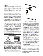
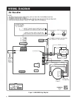
b. Low voltage wiring should be connected as shown in
c. Wire all other low voltage thermostat terminals to
NOTE:
If there is any other air moving device in the
duct work, consult the factory for a resolution.
Heater Kits
When electric heat packages with circuit breakers are field-
installed, the circuit breaker may be used as a disconnecting
means in most applications. Reference the NEC and local
codes for disconnect requirements.
If a heater kit is installed:
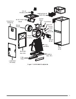
B64BM air handlers are shipped from the factory without
an electric heater kit installed. If electric heat is desired, a
heater kit may be purchased separately and field installed.
Determine the correct size heater kit for your unit by referring
to the heater kit installation instructions.
1. Connect the 2 wire plug of the air handler to the mating 2
wire plug of the heater kit.
2. Connect the line voltage leads to the circuit breaker or
terminal block provided.
3. Connect the heater kit plug with the mating receptacle on
the air handler control board.
If a heater kit is not installed:
1. Remove the 2 wire plug of the air handler by cutting the
wires and discarding the plug.
2. Strip the ends of the 2 air handler wires and connect to
the line-voltage leads with the 2 wire nuts provided.
3. Certain air handler models are equipped with blower limits
. These are left unconnected
if a heater kit is not installed.
Electronic Air Cleaner (EAC)
The unit has an output to power an electronic air cleaner
when the blower is running. This output is rated to 1.0 amp
STARTUP & ADJUSTMENTS
Before You Start the Unit
Prior to start-up, complete the following inspections:
√
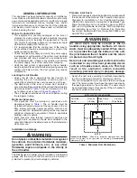
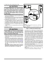
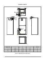
Verify the unit is level and properly located with adequate
clearances for servicing the unit as shown in
√
Check condensate drain line(s) for proper drainage.
√
Verify the surrounding area and top of the unit is free from
obstructions and debris.
√
Check all duct connections. Make sure the duct work is
adequately sealed to prevent air leakage.
√
Check all coil connections for leaks.
√
Verify that the line voltage power leads are securely
connected and the unit is properly grounded. Make sure
all doors are installed before restoring power to the unit
√
Verify the thermostat is wired correctly. Make sure all low
voltage wires are securely connected.
√
Verify the power supply branch circuit overcurrent protection
is sized properly.
√
Verify filter is properly and securely installed.
IMPORTANT:
Before starting the unit, install the initial
charge on units that are factory shipped with a nitrogen
holding charge:
1. Read all installation instructions first.
2. Purge the nitrogen holding charge.
3. Evacuate the unit to 350 - 500 microns.
4. Allow the unit to remain under vacuum for at least 30
minutes.
5. Weigh in the proper amount of new (or reclaimed)
refrigerant. Refer to the air conditioner or heat pump
installation manual for the proper type and quantity of
refrigerant.
Air Circulation
Running the Blower Continuously
Set the thermostat’s system mode to
OFF
and the thermostat’s
fan mode to
ON
. The blower motor should run continuously.
Check for air delivery at the register(s). Ensure that there are
no obstructions at the registers or in the ducts.
Turning the Blower Off
Set thermostat’s fan mode to
AUTO
, the blower will shut
down immediately.
System Cooling
1. Set the thermostat’s system mode to
COOL
and fan mode
to
AUTO
. Lower the thermostat’s temperature mode below
room temperature and observe that the blower energizes.
Check the air being discharged at the register is cooler
than room temperature. Verify unit refrigerant pressures
are in order. Blower should be turning in direction indicated
by arrow.
NOTE:
DO NOT alter unit wiring. Listen for any unusual
noises. Locate the source and correct as needed.
2. Allow the unit to run for several minutes and then set the
thermostat’s temperature above room temperature. Verify
the blower cycles off with the thermostat.
System Heating
1. Set the thermostat’s system mode to
HEAT
and the fan
mode to
AUTO
. Increase the thermostat’s temperature
above room temperature and observe that the blower
energizes. Check the air being discharged at the register
is warmer than room temperature.
2. Allow the unit to run for several minutes and then set the
thermostat’s temperature below room temperature. Verify
the blower cycles off with the thermostat.
Selecting Minimum Electric Heat Airflow
The minimum electric heat airflow setting controls the
minimum air flow that will be produced whenever electric
heater kits are used. When the electric heater kit is energized
along with a heat pump, the airflow may be higher depending
on the basic cooling/heat-pump airflow setting. The minimum
electric heat airflow is selected by the red blower wire on
3-speed models.
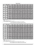
Blower Configurations
Determining Nominal System Capacity
To select the appropriate airflows for the air handler, the
nominal system capacity must be known. The nominal system
capacity is always the nominal capacity of the outdoor unit.
However, in some situations the nominal system capacity
may not be the same as the nominal capacity of the air
handler. Always refer to the nominal capacity of the outdoor
unit to determine the nominal system capacity. Use
as a guide for acceptable airflow CFM
(dependent on air handler cabinet size and nominal capacity
of the outdoor unit).


