background image

8

 CAUTION:

Before brazing the air handler, remove the core 
from the service port. Failure to comply may 
result in leakage at the service valve. Replace 
the core and cap once brazing is complete.

• 

B4VM-E Series air handlers are charged through service 
valves on the end of the liquid tube for each circuit. 
These must be removed before brazing the line sets. 

Refrigerant Line Connections

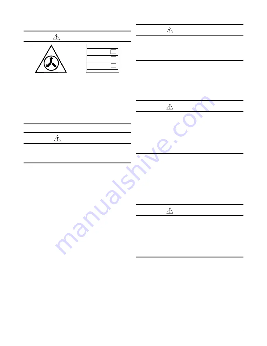
 WARNING:

The coil in the air handler is factory shipped with 
a nitrogen charge. Avoid direct face exposure 
or contact with valve when gas is escaping. 
Always ensure adequate ventilation is present 
during the depressurization process. Address 
any uncertainties before proceeding. Failure 
to comply with this warning could result in 
equipment damage, personal injury, or death.

NITROGEN

HEALTH

FLAMMABILITY

REACTIVITY

0 Minimal Hazard

1 Slight Hazard

1

0

0

 CAUTION:

This unit uses refrigerant R-410A. DO NOT use 
any other refrigerant in this unit. Use of another 
refrigerant will damage the unit.

•  The  installer  should  make  every  effort  to  ensure  the 

field installed refrigerant containing components of the 
system have been installed in accordance with these 
instructions and sound installation practices for reliable 
system operation and longevity.

•  The air handler coil does not contain a refrigerant charge. 

Refer to the installation instructions supplied with the 
outdoor unit for refrigerant charge information.

•  Always refer to the installation instructions supplied with 

the outdoor unit for piping requirements. The suction 
and liquid lines must be sized in accordance with the 
condensing unit specifications. See Table 3 (page 14) 
for liquid and suction line locations.

•  When  connecting  refrigerant  linesets  together,  it  is 

recommended that dry nitrogen be flowing through the 
joints during brazing. This will prevent internal oxidation 
and scaling from occurring.

•  Refrigerant tubing should be routed in a manner that 

minimizes the length of tubing and the number of bends 
in the tubing. It should be supported in a manner that 
prevents it from vibrating or abrading during system 
operation. Tubing should be kept clean of foreign debris 
during installation.

•  If precise forming of refrigerant lines is required, a copper 

tubing bender is recommended. Avoid sharp bends and 
contact of the refrigerant lines with metal surfaces.

•  Refrigerant  lines  should  be  wrapped  with  pressure 

sensitive neoprene or other suitable material where 
they pass against sharp sheet metal edges.

Connecting the Linesets

1. Remove grommets from line set holes.

 CAUTION:

To protect the Thermistor and EXV, it is 
recommended that a wet rag be wrapped 
around the suction line in front of the close 
off plate before applying heat. Failure to keep 
components cool during brazing may result 
in structural damage, premature equipment 
failure, or possible personal injury.

2. Unbraze and remove the cap on the suction line.
3. Route and cut both lineset tubes to proper length in 

accordance with the outdoor unit specifications. Verify 
the ends are round, clean, and free of any burrs.

4. Position grommet on line set with sufficient distance away 

from brazing area. Brazing processes can permanently 
damage grommets.

5. Connect the suction and liquid lineset tubes.

 CAUTION:

To protect the Thermistor and EXV, it is 
recommended that a wet rag be wrapped 
around the suction line in front of the close 
off plate before applying heat. Failure to keep 
components cool during brazing may result 
in structural damage, premature equipment 
failure, or possible personal injury.

6. Braze the individual connections with dry nitrogen 

flowing through the joints. NOTE: This will prevent 
internal oxidation and scaling from occurring.

7. Wrap the refrigerant lines with pressure sensitive 

neoprene or other suitable material especially where 
the lines enter the opening in the sheet metal.

8. Evacuate the system of moisture and non-condensables 

to prevent low efficiency operation or damage to the 
unit. The suggested range of evacuation is 250 - 500 
microns.

Summary of Contents for B4VM-E

Page 1: ...type of equipment Improper installation service adjustment or maintenance may cause explosion fire electrical shock or other hazardous conditions which may result in personal injury or property damage...

Page 2: ...before servicing this equipment Pay attention to all safety warnings and any other special notes highlighted in the manual Safety markings are used frequently throughout this manual to designate a deg...

Page 3: ...operations Installthisunitonlyinalocationandpositionasspecified on pages 4 5 This unit is designed only for Indoor installations and should be located with consideration of minimizing the length of t...

Page 4: ...r service access and noise The dimensions of the room or alcove must be able to accommodate the overall size of the unit and the installation clearances listed in Figure 1 Physical dimensions for this...

Page 5: ...cated in the bottom of the unit Accessing the filter does not require tools and can be removed from the front of the unit by removing the filter door See Unit Maintenance page 13 for filter sizes and...

Page 6: ...never the supplyorreturnairductspassthroughthefloor Thegasket should be positioned between the duct unit and floor Upflow Installations All air handlers are factory shipped ready for upflow installati...

Page 7: ...horizontal drain pan IMPORTANT If the webbing is not removed the condensate will not drain properly and ceiling damage may occur 3 Insert the plug from horizontal drain pan into the open and unused d...

Page 8: ...r that minimizes the length of tubing and the number of bends in the tubing It should be supported in a manner that prevents it from vibrating or abrading during system operation Tubing should be kept...

Page 9: ...runionwithasmallpaintbrush If bubblingisobserved theconnectionisnotadequately sealed 11 Replace all grommets and properly dispose of all removed parts Condensate Drainage CAUTION The air handler must...

Page 10: ...occur Do not use gas piping as an electrical ground This unit must be electrically grounded in accordance with local codes or in the absence of local codes with the National Electrical Code ANSI NFPA...

Page 11: ...MOP Circuit A Circuit B Circuit C 240 NONE 5 8 15 5 8 15 005H 30 8 40 30 8 40 008H 44 8 50 44 8 50 010H 55 8 60 55 8 60 015H 80 8 90 55 8 60 25 0 30 020H 105 8 125 55 8 60 50 0 60 025H 130 8 150 55 8...

Page 12: ...t user manual Dehumidification The iQ Drive system may provide some dehumidification by lowering the airflow to increase the amount of humidity that is removed from the circulating air during cooling...

Page 13: ...in place Verify that the thermostat is properly installed and is not being affected by drafts or heat from lamps or other appliances Toachievethebestperformanceandminimizeequipment failure it is reco...

Page 14: ...D B 43 5 16 19 11 16 18 1 4 No Tall B 49 5 16 19 11 16 18 1 4 No C 55 15 16 22 7 16 21 Yes 3 4 3 4 3 4 13 1 1 4 1 5 8 1 7 8 1 1 4 3 1 4 2 5 8 11 8 K O Typ 1 3 4 K O Typ 1 7 8 3 5 8 5 5 8 DETAIL D 3 1...

Page 15: ...tor Mount Kit Blower Motor Transformer Capacitor Circuit Breaker 60A Heating Element Assembly Filter Tracks Blower Wheel Blower Housing Control Board Filter Door Upper Door Assembly Lower Door Assembl...

Page 16: ...EXV Control Board R R 410A 1 2 3 4 5 6 7 8 ON OFF R 22 THERM THERM PRESS C Y COMM EXV C R G Y Y2 O W1 W2 Y1 24VAC COM FUSE P2 P3 X13 COM X13 HEAT X13 COOL XFMR L1 VSPOWER L1 L2COM L2 L2 Figure 10 X13...

Page 17: ...COM 24 VAC COM L1 L1 XFMR W2 W1 O Y Y2 HEATER PLUG KIT G R C RED YELLOW WHITE GREEN BLACK RED GREEN BLACK WHITE RED RED RED GRAY YELLOW WHITE BLACK TO OUTDOOR UNIT BLACK WIRES EXV 6 WIRE CABLE CABLE C...

Page 18: ...18...

Page 19: ...19...

Page 20: ...sareprimarilyintendedtoassistqualifiedindividuals experienced in the proper installation of this appliance Some local codes require licensed installation service personnel for this type of equipment P...

Reviews: