NanoQuest Simple Installation Guide
DOC0053_Issue2.2
Scope
This document explains the initial installation of the NanoQuest unit so that it can be used to control
basic access through a door. For further installation and programming instructions, download the
full Instruction Manual from
http://www.nortechcontrol.com/support/download-documents/
Before Installation
Check that the box contains the following items:
1 x NanoQuest (2-part) unit
2 x mounting screws (No.6 x 1.25”)
1 x cover securing screw
2 x Master proximity cards
1 x varistor
1 x Mounting Template
You will also need unassigned proximity cards or card packs purchased separately.
The NanoQuest requires a power supply of between 9 and 16V DC. We recommend that an
appropriate 12V DC power supply unit or mains adaptor is made available to supply power to the
NanoQuest. The NanoQuest requires less than 70mA at 12V.
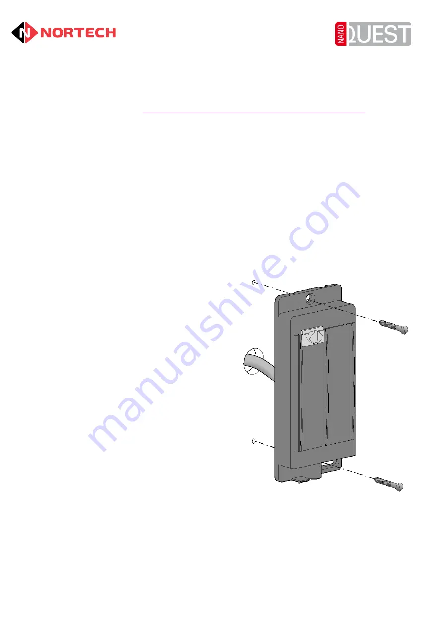
Mounting the NanoQuest
1) Identify a suitable location for the NanoQuest. It
should be located at a convenient height near to
the door that it controls. The unit is waterproof
and suitable for exterior use but it must not be
used for an exterior door without another means
of securing the door. (For example, a dead lock
secures the door at night with NanoQuest
controlling access by staff during the day).
2) Use the supplied template to mark out the
positions of the holes for screw fixings and cable
access, and drill appropriate sized holes.
3) Remove the cover from the NanoQuest by
inserting the tip of a terminal screwdriver into the
small slot next to the screw hole at the bottom of
the NanoQuest, and pressing lightly to release
the securing catch while you separate the cover
from the body at the base.
4) Feed the cable through the wall and terminate it
either inside the PSU enclosure or in a suitable
tamperproof terminal box.
5) Secure the NanoQuest to the wall.
6) Fit the cover and secure with the supplied
securing screw once the NanoQuest has been
fully installed.
Wiring the NanoQuest
Connect the unit as shown on the next page (always fit the varistor as close to the locking device
as possible). If a door strike is used and a door handle is left in use on the inside of the door,
connection to the free exit button may not be required. See the full NanoQuest Instruction Manual
for the connection of additional items such as local alarms and door contacts.


