


2.
The old cylinder must be drained completely
before removing. This is done by pushing the auto
on/off/drain switch to the “drain” position.
3.
When completely drained, push the auto
on/off/drain switch to the “off” position.
4.
Open the main disconnect during the entire
cylinder change operation.
5.
The power wires to the cylinder are attached by
cylinder plugs to the electrode pins on top of the
cylinder. Pull these plugs vertically off the pins.
See Figure # 4.
6.
Using slot screwdriver, loosen the steam hose
clamp(s) and pull steam hose off vertically.
7.
The cylinder is now ready to be lifted out of the
unit.
INSTALLING THE NEW CYLINDER
1.
The reverse procedure should be followed to
install a new cylinder. The main disconnect is to
be left open until the cylinder is completely
installed and reconnected.
2.
Ensure that the cylinder mounting stubs are
seated properly in the allotted side mounting slots
within the unit.
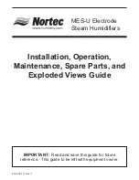
3.
The white sensor plug on all units is for the sensor
pin, which always goes on the single pin offset
from the others. See Figure # 5.
4.
Ensure that cylinder plugs are very snug on the
pins.
5.
For loose fitting plugs, a temporary solution is to
squeeze plugs with a pair of pliers before
installing. Since loose plugs may generate
enough heat to melt and destroy the plug and
cylinder new plugs must be ordered.
MAINTENANCE
WARNING! The plumbing and electrical
compartments contain high voltage components and
wiring. The access cover is attached with screws.
Access should be limited to authorized personnel only.
EXTENDED SHUTDOWN
Before disconnecting power to the humidifier for a
period of extended shutdown, ALWAYS DRAIN the
cylinder first. Otherwise, the electrodes are subject to
harmful corrosion which drastically shortens the
cylinder life. Do NOT leave the switch in the DRAIN
position indefinitely as the drain coil could burn out.
Leave the switch in the OFF position and “open” the
main external fused disconnect to stop power to the
humidifier. Close the shut off valve in the water supply
line feeding the humidifier.
TROUBLESHOOTING
TERMS USED
F.L.A. (Full Load Amps): Refers to amps listed on
the humidifier specification label.
SHORT CYCLING: When the ‘on time’ of the
humidifier is less than ten minutes upon a call for
humidity. To correct short cycling, all humidifiers have
a capacity adjustment which allows the output of the
humidifier to be reduced to as low as 20% of rated
output, thus extending the ‘on time’ required to
maintain output.
FOAMING: The phenomenon which can occur in
water when the impurities, already in the water reach
an excess concentration as a result of boiling away
pure water and the continued boiling action agitating
the contained water. The humidifier electronics are
designed to prevent this occurrence although in
extreme cases, water will foam with little concentration
making it necessary to have the drain time of the
water, contained in the cylinder, increased. Foaming
- 4 -
Figure #5
Plugs
Cylinder
Plug
Cylinder Pin
Cylinder Pin
Cylinder Pin
Cylinder Pin
Cylinder Pin
White
Sensor Plug
Sensor Pin
Sensor Pin
3Ø
1Ø


