47
Installation
Nortec EL
2582302_C_EN_1611
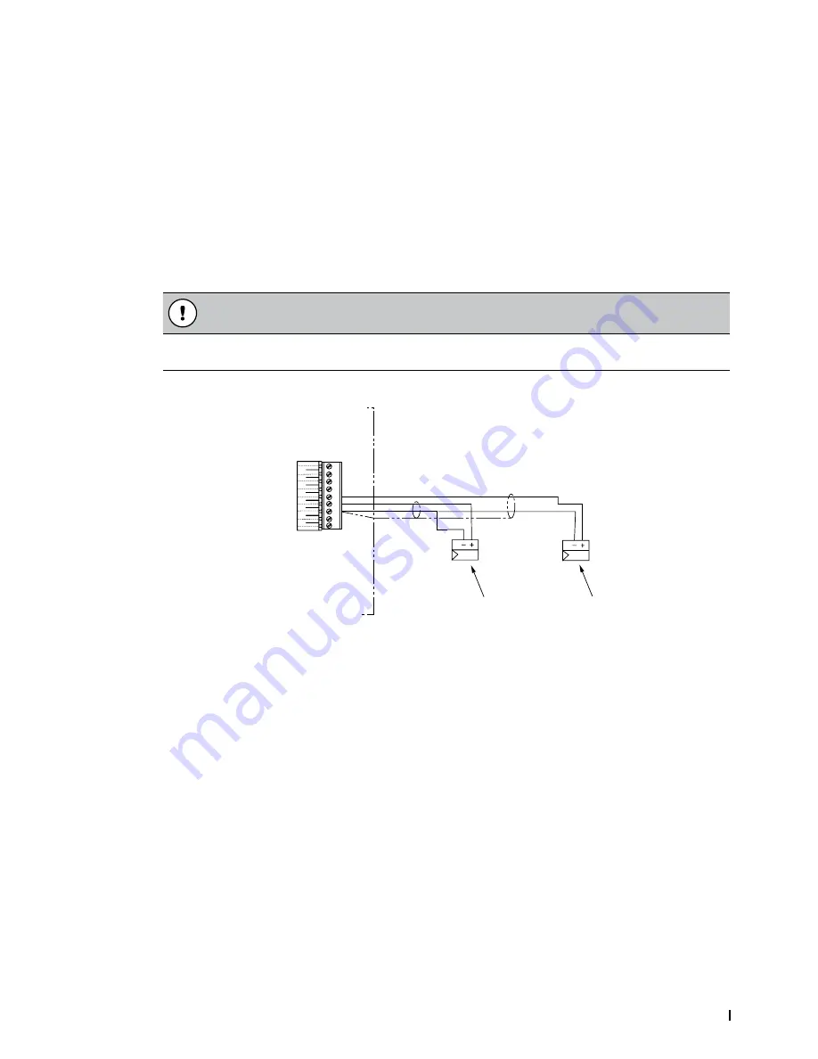
5.8.3.4 Modulating Demand or Humidity Signal
Connect an external humidity sensor input or direct demand modulating input to terminal points "3" and
"4" in the low voltage terminal strip. Refer to
Figure 24 on page 41
and
Figure 29
. The permissible control
signal input values are shown in
Table 8 on page 39
.
Do not connect multiple modulating signals to the same modulating input on the humidifier. If necessary,
a second modulating signal can be connected to terminal point "5" and "3", using terminal point "3" as
common. Make sure that Control Channels is set to "Dual" in the control software to utilize the second
modulating signal – refer to the Operation and Maintenance Manual.
Alternately, transducer signals or demand signals can be written to the humidifier via a valid digital com
-
munication protocol. Set Source to "Modbus", "BACnet IP", "BACnet MSTP" or "Lonworks".
The signal cable must lead into the control cabinet through a cable gland or grommet. If a shielded signal
cable is used, connect the shielding to terminal point "3".
CAUTION!
If the shielding of the signal is already connected to a potential or a grounded conductor, do not
connect it to terminal point "3".
Figure 29:
External
1
LV
2
8
7
6
5
4
3
2
9
1
Modulating Demand or Humidity Signal Connection
1 Modulating demand or humidity sensor signal
2 Modulating demand or humidity sensor signal (additional)