


P.O. Box 40525, Houston, Texas USA 77240-0525
Tel: 713·466·3552 · Fax: 713·896·7386
www.norriseal.com
2700A — ©2015, February, 2015
O
PERATING AND
M
AINTENANCE
M
ANUAL
Series 2700A Control Valve
2.0 Valve Maintenance
Before attempting any repairs, isolate
the control valve from the system and
make sure that all pressure is released
from the valve body, both up and
downstream. Shut off and vent supply
and signal air lines to the actuator.
1. Isolate the valve from the
process.
2. Shut off all control and supply
lines to the actuator.
3. Release the process pressure.
4. Vent the actuator loading
pressure.
Valve parts are subject to normal wear
and must be inspected and replaced
as necessary, with the frequency
of inspection depending upon the
severity of the repair needed. The
following sections describe the
procedures for disassembling and
reassembling the valve for normal
maintenance and troubleshooting.
All maintenance operations may
be performed while the valve body
remains in line, as long as the line is
not in service and/or is isolated from
active process by block valves. Table
2 lists the maintenance schedule for
the valve assembly. Table 5 provides
assistance in troubleshooting valve
operation.
NOTE: An increase in plug seating
force will also require an increase in the
diaphragm supply pressure required to
fully open the valve.
NOTE: Excessive adjustment of the
spring to increase seating force may
shorten the valve stroke preventing the
valve from opening fully.
Direct (fail open):
Loosen
the lock nut on the adjusting
nut below the spring.
Turn the adjusting nut
clockwise to increase the
spring’s preload and turn it
counterclockwise to reduce
the preload. Retighten the
nut after adjustment.
NOTE: In a direct setting, any increase
in pressure may produce an increase
in plug seating force when the valve is
closed. Do not exceed 55 psi supply
pressure.
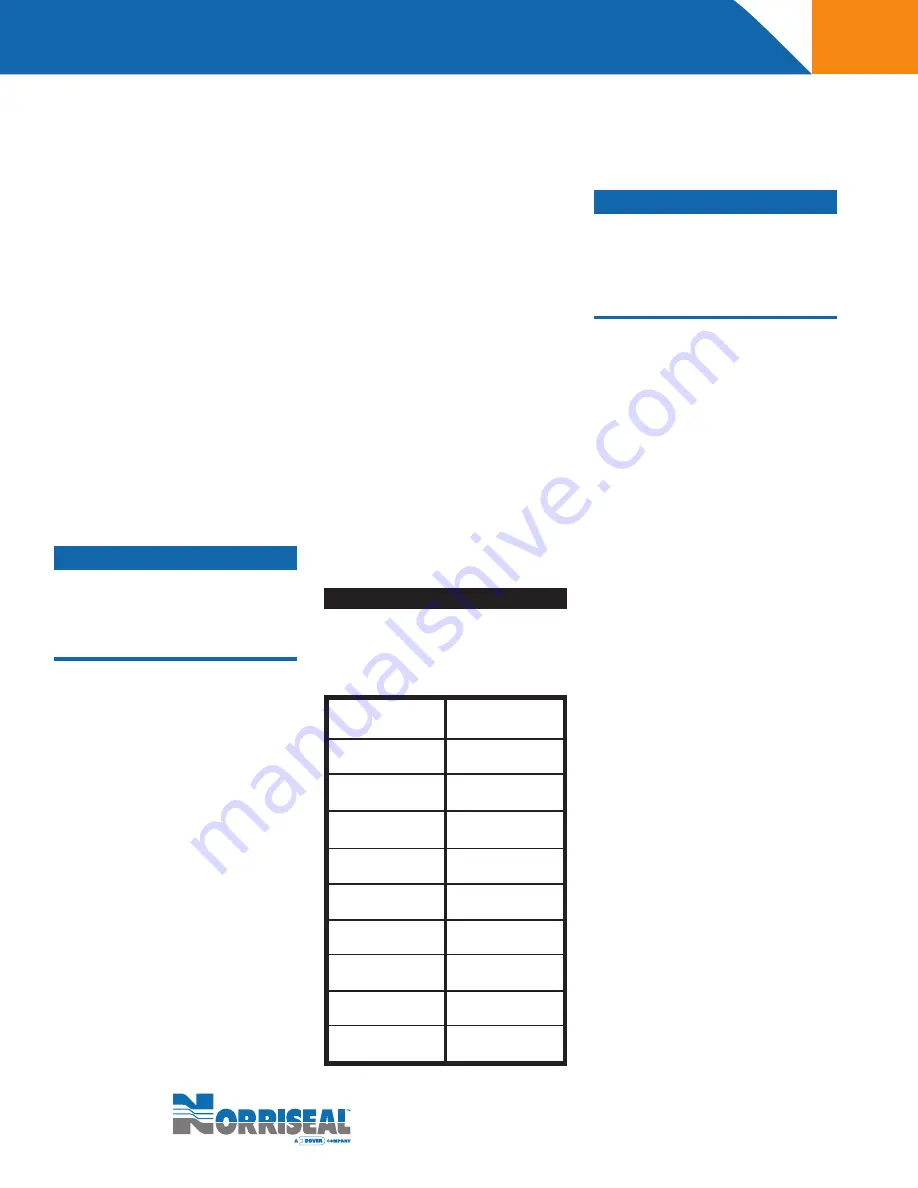
Stem travels for valves with full size
trim are listed below. For valves with
reduced or restricted trim, stem travel
may be less than the value shown.
Page 2 of 12
pipeline. For threaded (NPT)
bodies, use pipe thread sealant.
The bodies are rated ANSI 150,
300, 600, 900, 1500 or 2500
class. Do not install the valve
in a system where the working
pressures exceed the limitations
noted on the nameplate.
Where piping is insulated
do not
insulate the valve above the
valve bonnet.
Connect the instrument air to the
actuator or positioner connection.
Refer to the nameplate for
maximum instrument air pressure.
Check for proper valve operation
by cycling the actuator several
times and observing the stem
movement.
Do not exceed the maximum instrument
air pressure stamped on the valve
nameplate. Under no circumstances
should the actuator loading pressure
exceed 55 psi.
Actuator springs are pre-set at
a factory and may require ad-
justments to suit your specific
operating conditions. To adjust
the spring setting, complete the
following:
Reverse (fail close)
:
Loos-
en the lock nut on the stem
below the spring, and turn
the adjusting nut above
it clockwise to increase
the spring’s pre-load and
plug seating force. This will
achieve a more secure shut-
off. Turn the adjusting nut
counterclockwise to reduce
preload. Retighten the nut
after adjustment.
WARNING!
WARNING!
5.
6.
7.
8.
a.
b.
T A B L E 1
BODY SIZE (in)
1.00
1.50
2.00
3.00
4.00
6.00
8.00
10.00
12.00
STEM TRAVEL (in)
0.75
1.00
1.25
1.50
2.00
2.75
4.00
4.00
4.00