5
NM 3526 16 Elements antenna system adjustments - LLZ
5.1
Mechanical alignments of antenna array
5.1.1
Right angle points with reference to runway centre line
The alignment of the antenna array perpendicular to the runway centreline should be carried
out to an accuracy of 0.01°.
This corresponds to within 4 mm accuracy at positions antenna 1 and antenna 16. A theodo-
lite should be utilised.
5.1.2
Spacing distance between LPDA’s
Check that the spacing between each LPDA is according to dimensions given in dwg.no.
16362A3.
Tolerance: ±5 mm.
5.1.3
Vertical alignment of LPDA support masts
On each rear support mast for LPDA check with waterlevel that mast is vertically aligned in
both planes.
5.1.4
Azimuth alignment of LPDA’s
Determine a fixed point as far as possible along the extended centreline not less than approx-
imately 3000 m from the antenna array.
On each LPDA utilise the top horizontal line composed of the two half sections of the radome
to point toward the fixed point.
If necessary adjust the LPDA horizontally by adjusting the mast supports on the front mast, so
that the extended radome top line ends at the fixed point.
5.2
Electrical measurements
5.2.1
CSB and SBO cables
Course Tx cables.
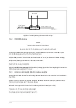
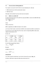
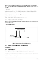
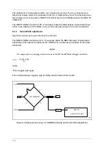
The CSB and SBO cable between the cabinet and MCU must be of equal electrical length.
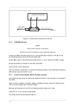
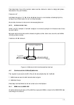
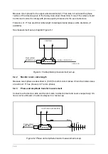
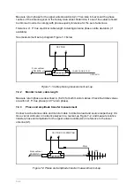
Utilise a vector voltmeter or network analyser in a test set-up as in Figure 5-1.
Measure open cable return phase for each cable.
Refer to CSB cable as zero phase and measure the return phase for the SBO cable. The
cable pair must be matched within ±3.0° return phase, equal to ±1.5° true phase.
Clearance Tx cables.
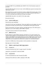
Repeat the procedure 1.2.1 for CLR Tx CSB and SBO cables
Summary of Contents for NM 7000 Series
Page 7: ...1250 5 167580 17 1 1 6 67 0 167 7 21 200 66 21 1 1 22 1DYLD YLDWLRQ 6 ...
Page 11: ...1250 5 167580 17 1 1 6 67 0 167 7 21 200 66 21 1 1 22 1DYLD YLDWLRQ 6 Figure 2 3 ...
Page 13: ...1250 5 167580 17 1 1 6 67 0 167 7 21 200 66 21 1 1 22 1DYLD YLDWLRQ 6 ...
Page 19: ...1250 5 167580 17 1 1 6 67 0 167 7 21 200 66 21 1 1 22 1DYLD YLDWLRQ 6 ...
Page 21: ...1250 5 167580 17 1 1 6 67 0 167 7 21 200 66 21 1 1 22 1DYLD YLDWLRQ 6 ...
Page 23: ...1250 5 167580 17 1 1 6 67 0 167 7 21 200 66 21 1 1 22 1DYLD YLDWLRQ 6 ...
Page 25: ...1250 5 167580 17 1 1 6 67 0 167 7 21 200 66 21 1 1 22 1DYLD YLDWLRQ 6 ...
Page 27: ...1250 5 167580 17 1 1 6 67 0 167 7 21 200 66 21 1 1 22 1DYLD YLDWLRQ 6 ...
Page 31: ...1250 5 167580 17 1 1 6 67 0 167 7 21 200 66 21 1 1 22 1DYLD YLDWLRQ 6 ...
Page 45: ...1250 5 167580 17 1 1 6 67 0 167 7 21 200 66 21 1 1 22 1DYLD YLDWLRQ 6 ...
Page 55: ...1250 5 167580 17 1 1 6 67 0 167 7 21 200 66 21 1 1 22 1DYLD YLDWLRQ 6 ...
Page 65: ... ...
Page 81: ... ...
Page 111: ... ...
Page 129: ... ...
Page 132: ... ...
Page 134: ...1250 5 167580 17 1 1 6 67 0 167 7 21 200 66 21 1 1 22 1DYLD YLDWLRQ 6 ...
Page 150: ...1250 5 167580 17 1 1 6 67 0 167 7 21 200 66 21 1 1 22 1DYLD YLDWLRQ 6 ...
Page 158: ...1250 5 167580 17 1 1 6 67 0 167 7 21 200 66 21 1 1 22 1DYLD YLDWLRQ 6 ...

