background image

24

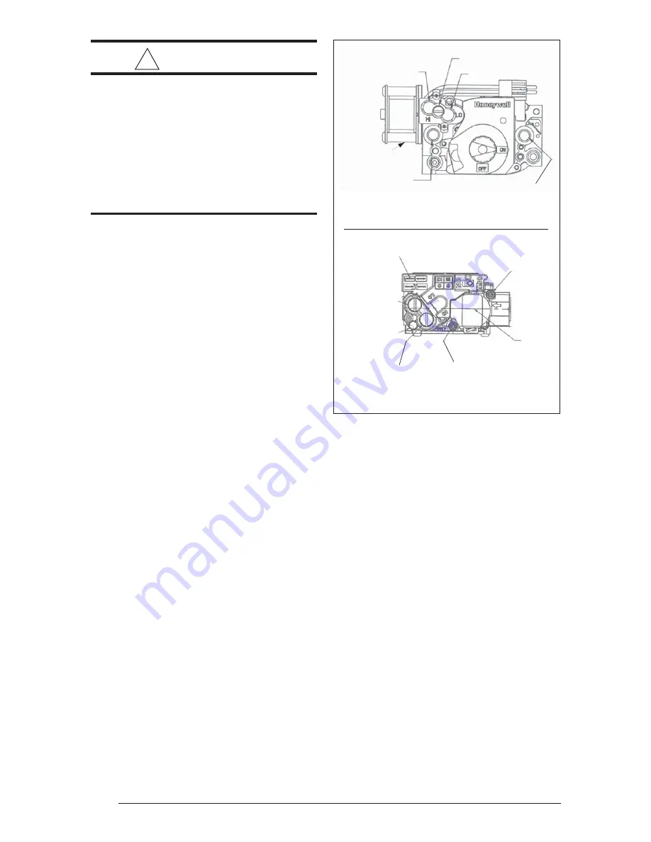
Figure 20. Gas Valve

 (Honeywell shown)

 (White Rodgers shown)

(4) QUICK DI

S

CONNECT TERMINAL

S

1

S

S

TAGE

REGULATOR COVER
REGULATOR ADJU

S

T

BENEATH THI

S


S

CREW

VENT (.

33

0 DIA.

+DFT. PO

S

T)

ACCEPT

S

 5/16” HO

S

E

CONNECTION

2ND 

S

TAGE

REGULATOR COVER
REGULATOR ADJU

S

T

BENEATH THI

S


S

CREW

OUTLET PRE

SS

URE

PO

S

S

ET 

S

CREW: 

3

/

3

2

HEX HEAD (.

33

9 DIA. +DFT.)

ACCEPT

S

 5/1

8”

 HO

S

E CONNECTION

CONTROL
LABEL

INLET PRE

SS

URE PO

S

T

S

ET 

S

CREW: 

3

/

3

2

 HEX HEAD

(.

33

9 DIA. +DFT.)

ACCEPT

S

 5/1

8”

HO

S

E CONNECTION

VENT FITTING FOR 90 PLU

S

EFFICIENT APPLIANCE

S

LOW 

S

TAGE ADJU

S

TMENT

UNDER VENT CAP

HIGH 

S

TAGE ADJU

S

TMENT

UNDER VENT CAP

OUTLET PRE

SS

URE TAP 

1/

8

 NPT

INLET PRE

SS

URE TAP 

1/

8

 NPT

2-

S

TAGE

OPERATOR

value based on sea level can be obtained from
your  local gas utility. The heating value of gas
at high altitude is always lower than the sea level
heating value. The heating values used in Tables
10 and 11 are based on sea level values.

Pressure Switch Conversion for
High Altitude Applications

These units are factory equipped to operate
between zero and 8000 feet above sea level.  For
higher altitude applications, you may need to
replace the vent pressure switch in addition to the

main gas burner orifices.

Natural Gas High Altitude
Conversion

All factory shipped furnaces are ready to operate
between zero and 4999 ft. above sea level.  For
higher altitudes (between 5000 and 10,000 ft.
above sea level), conversion can be achieved
simply by adjusting the furnace manifold
pressure as shown in Tables 6 and 7.

!

 WARNING:

This furnace was equipped at the fac-
tory for use with natural gas only.  A
special kit, supplied by the manufac-
turer, is required to convert the fur-
nace to operate on LP/propane  gas.
Failure to use the proper conversion
kit can cause fire, explosion, property
damage, carbon monoxide poisoning,
personal injury, or death.

MANIFOLD PRESSURE
ADJUSTMENT

Manifold pressures for low and high stages are
independently adjustable. Adjustment tap
locations on the valve are shown in Figure 20.
Manifold pressure would be adjusted below
procedure:

-

Turn off gas shut off valve outside furnace.

-

Install manometer on the gas valve at the
outlet pressure tap.

-

Turn on the shut off. Run furnace at high
fire and set manifold pressure. Also set
manifold pressure while running at low fire
(refer to Tables 6 and 7.)

-

Ensure plug is tight after removing
manometer.

Conversion

Conversion of this furnace to use LP/propane
gas must be made by qualified service
personnel, using 

only

  approved parts.

IMPORTANT NOTE: When converting a low
NOx furnace from Natural Gas to LP/Propane
Gas, it is necessary to remove the NOx

baffles from the furnace.

HIGH ALTITUDE CONVERSION

High Altitude Application

Conversion of this furnace to replace the pressure
switch or to utilize LP/propane gas must be made
by qualified service personnel, using factory
authorized or approved parts. High altitude
applications with this furnace can be field
performed by a simple adjustment of manifold
pressure, and if necessary changing the orifices
and the vent pressure switch. The changes
required depend on the installation altitude and
the heating value of the gas. The gas heating

Summary of Contents for *TE Series

Page 1: ...ervice or maintenance can cause injury or property damage Re fer to this manual for assistance For additionalinformationconsultaquali fied installer service agency or the gas supplier FOR YOUR SAFETY...

Page 2: ...upport 15 Location of Outdoor Terminations 18 HorizontalVenting 18 Vertical Venting 19 Vent Freezing Protection 20 ConcentricVentTermination 20 DrainageofCondensateFromFurnace 20 GasSupplyandPiping 21...

Page 3: ...ts A B Combustion Air Vent 3 See Fig 15 for sizes 1 1 2 x 3 1 2 Dia Opening for Gas Connection 3 4 3 4 3 4 22 1 2 Exhaust Vent Combustion Air Inlet 1 1 2 x 3 1 2 Dia Opening for Gas Connection C 2 PVC...

Page 4: ...d furnace for installation in a residential garage must be installed as specified on Page 7 of these instructions 10 The furnace is not to be used for temporary heating of buildings or structures unde...

Page 5: ...ices both the appliance and the carbon monoxide detector b Have battery back up power c Meet ANSI UL 2034 Standards and comply with NFPA 720 2005 Edi tion and d Have been approved and listed by a Nati...

Page 6: ...erage The 90 upflow furnace can be installed hori zontally in an attic basement crawl space or alcove This furnace can be installed horizon tally to the clearances listed in Table 6 on a platform or o...

Page 7: ...itch Grey Tubing Soft Tubing 1 4 Vinyl Cap Grey Tubing Drain Trap Soft Tubing PVC Tee Soft Tubing Looped to Provide a Drain Trap 3 to 2 Reducer Optional Drainage Port is Downard Reducer Bushing Altern...

Page 8: ...ice such as a fireplace insert stove etc CIRCULATINGAIRSUPPLY Plenums and air ducts must be installed in accordance with the Standard for the Installa tion of Air Conditioning and Ventilating Systems...

Page 9: ...mes contaminated with various household chemicals which can cause severe corrosion in the furnace combus tion system NOTE If the furnace is operated without ad equate air for combustion and ventilatio...

Page 10: ...WARNING Furnacesinstalledwithcombustionair drawn from a heated space which in cludes exhaust fans fireplaces or otherdevicesthatmayproduceanega tive pressure should be considered confined space insta...

Page 11: ...90 degree elbow 3 Do not include termination elbows in calculation of vent length 4 This table is applicable for elevations from sea level to 2000 ft For higher elevations decrease vent pipe lengths b...

Page 12: ...ir Duct must be at least 1 sq in per 4 000 Btuh of total input rating Ducts must extend above attic insulation Air Duct must be at least 1 sq in per 4 000 Btuh of total input rating Ventilation Louver...

Page 13: ...roper size and horizontal pitch as required in the National Fuel Gas Code ANSI Z223 1 or the CAN CGA B149 Instal lation Codes and these instructions Determine that there is no blockage or restriction...

Page 14: ...installation requires breakable connections in the piping Note that a maximum of two couplings per pipe are allowed UpflowFurnaces Combustion Air Pipe Exhaust Vent Cabinet 5 Support System on Vertica...

Page 15: ...eter of the piping can be chosen for which the equivalent vent length is less than the maximum allowable vent length Returning to our example we consult Table 3 and deter mine that for a 120 000 Btu h...

Page 16: ...cm for appliances 10 000 Btuh 3 kW 9 inches 23 cm for appliances 10 000 Btuh 3 kW and 50 000 Btuh 15 kW 12 inches 30 cm for appliances 50 000 Btuh 15 kW C Clearance to permanently closed window D Ver...

Page 17: ...0 000 Btuh 3 kW and 100 00 Btuh 30 kW 36 inches 91 cm for appliances 100 00 Btuh 30 kW 4 feet 1 2 m below or to side of opening 1 foot 300 mm above opening C Clearance to permanently closed window D V...

Page 18: ...ence in installation and service Location of Outdoor Terminations Horizontal Venting Vent and combustion air intake terminations must be as shown in Figures13 and 14 Vent termination clearances shall...

Page 19: ...e by closely fitting standard couplings The face plates are retained on both sides of the wall by the couplings and the gasket is retained against the wall by the outer face plate Face plates must be...

Page 20: ...GEOFCONDENSATE FROMFURNACE The condensate drainage system is internal to the furnace It is not recommended to connect additional traps to the exterior of the furnace Doing so will have adverse effects...

Page 21: ...required as NORDYNE cannot be held responsible for water leakage which occurs due to loose hose connections or improperly sealed drain line pipes GAS SUPPLY AND PIPING This furnace is equipped for eit...

Page 22: ...olutionmadespecificallyforthe detection of leaks to check all connec tions A fire or explosion may result causing property damage personal injury or loss of life IMPORTANT NOTE When pressure testing g...

Page 23: ...LP Gas Sea Level Heating Value of 2 500 Btu hr Elevation feet above sea level zero to 1999 2000 to 4999 5000 to 5999 6000 to 7999 8000 to 10000 Manifold Pressure Setting in WC Full Input 10 8 5 10 9...

Page 24: ...bles 6 and 7 WARNING This furnace was equipped at the fac tory for use with natural gas only A special kit supplied by the manufac turer is required to convert the fur nace to operate on LP propane ga...

Page 25: ...e done in accor dancewiththecurrentCanadianElectricalCode CSA C22 1 Part 1 and or local codes If any of the original wire as supplied with the furnace must be replaced it must be replaced with wire ha...

Page 26: ...ower will operate at high speed b Low fire only operation To set low fire only operation program the second stage temperature higher than the de sired room temperature refer to Ther mostat controller...

Page 27: ...ing fixtures and convective load ing from warm air registers or electrical appli ances START UPANDADJUSTMENTS Prior to start up verify that 1 The line voltage power leads are securely connected that t...

Page 28: ...rating plate At alti tudes above 2000 feet it must not exceed that on the rating plate less 4 for each 1000 feet Follow the procedure below to determine the firing rate 1 Shut off all other gas fired...

Page 29: ...at the optimum airflow rate for the capacity Detailed operation is described in the cooling unit instal lation instructions and control manual Verifying and Adjusting TemperatureRise Verify that the...

Page 30: ...mit switch makesurethattheblowerdoorisinplaceandthat there is power to the furnace Completely block the return airflow to the furnace by installing a close off plate in place of or upstream of the fil...

Page 31: ...WHITE WHITE GRAY BLACK WHITE GREEN BLACK BLACK RED BLACK YELLOW ORANGE WHITE GREEN GREEN GREEN GREEN BLACK RED RED PLUG CONNECTOR BLACK BROWN BROWN BLACK C W2 RH R W1 H 0 Y2 Y1 G L V A B GD OD ID GD T...

Page 32: ...is recommended that the furnace be checked yearly At a minimum this check should include the following items WARNING Toavoidelectricshock personalinjury ordeath disconnecttheelectricpower before perfo...

Page 33: ...9 BlowerDoor Switch 10 VentSafetySwitch 11 LowVoltage Transformer 12 Supply Air Limit Switch 3 4 12 18 14 7 9 11 23 5 6 22 10 16 13 15 21 8 17 20 2 1 13 CirculatingAir BlowerAssembly 14 InducedDraft...

Page 34: ...for the heating cool ing and fan modes are described below Refer to the field and furnace wiring diagrams Figures 22 and 25 Heating Mode 1 On a call for heat the thermostat sends signal to the interfa...

Page 35: ...n blower stages to lower speed Low fire is satisfied the low fire will be de energized 10 The inducer is de energized after a 30 second postpurge 11 The circulating air blower remains on for 120 secon...

Page 36: ...d ______ Gas Line Pressure ____________________ in water column with furnace operating Manifold Pressure ____________________ in water column with furnace operating Is there adequate fresh air supply...

Reviews: