7
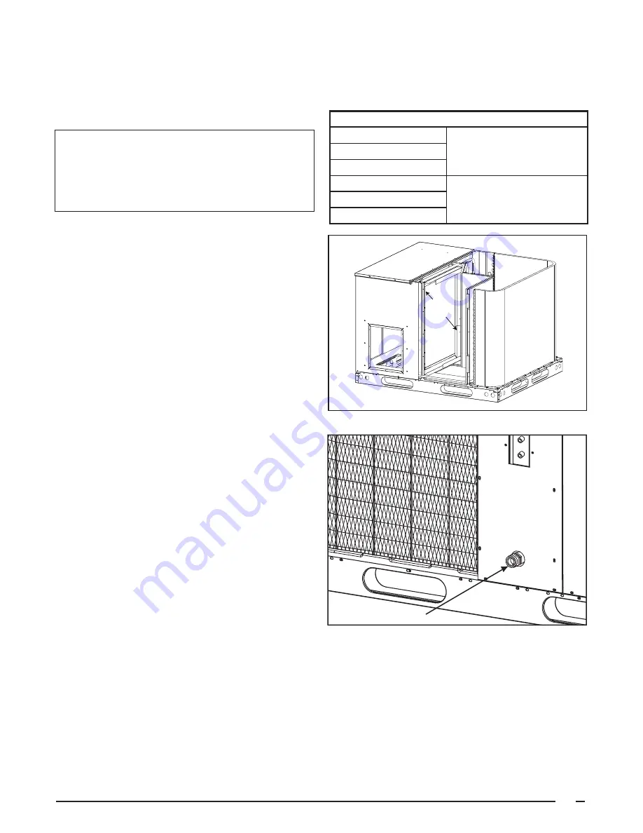
Figure 3a. Internal Filter Rack Location
Securing
Screw
adjustment screw from the inside of the rack, and the
(1) screw securing the assembly to the coil located
on the left leg of the rack. The assembly can easily be
collapsed and removed from the unit. See Figure 3a for
fi lter rack securing screw locations.
IMPORTANT NOTICE TO INSTALLER:
After installing
or replacing the fi ltration system for this unit, add
the following marking on the fi lter service panel or
reasonably adjacent thereto:
“Replace filter(s)
installed in your system only with the same
dimensional size fi lters that are being replaced.”
For single phase downfl ow installations only, an internal
fi lter accessory kit can be ordered. For horizontal instal-
lations, the air fi lter system must be installed in the
return air ductwork. All return air to this unit must pass
through the fi lter(s) before entering the evaporator coil.
INSTALLING FILTERS IN THE FACTORY INSTALLED
FILTER RACK
1. Remove access panel screws from return air panel.
(You may want to loosen the unit’s Top Panel screws
that are located near the top edge of the access panel.
The access panel was designed to be captured under-
neath the Top Panel.)
2. To install media, slide fi lter between guide channels
of fi lter rack. The fi rst fi lter will easily drop into place.
(Check to insure that the bottom of fi lter is within the
channels of the rack.) Insert the second media in the
same manner as the fi rst. (Again, check to insure that
the media is captured by the channels of the fi lter rack.
3. Replace access cover by sliding the top edge of
panel under the lip of the unit’s Top Panel. Secure Ac-
cess Panel by replacing the screws.
REMOVAL OF FILTERS FROM FACTORY INSTALLED
FILTER RACK
1. Remove access panel screws from return air panel.
(You may want to loosen the unit’s Top Panel screws
that are located near the top edge of the access panel.
The access panel was designed to be captured under-
neath the Top Panel.)
2. To remove upper media, gently pull fi lter through the
Access Panel opening.
3. To remove lower media, lift medial to top of Filter
Rack and remove in the same manner as described in
step two.
4. Replace old fi lter with new media per the Insertion
Instruction detailed above.
Condensate Drain —
Condensate is removed from the unit
through the 3/4” female pipe fi tting located on the front side of
the unit. (See
Figure 4
.) Install a 2 inch deep condensate trap
in the drain line of the same size and prime with water.
When connecting rigid drain line, hold the female fi tting with
a wrench to prevent twisting.
Do not over tighten!
Refer to
local codes and restrictions for proper condensate disposal
requirements.
UNIT INSTALLATION
Ground Level —
When installing the unit at ground level (See
Figure 5
), provide a concrete mounting pad separate from the
building foundation. The pad must be level to insure proper
Figure 4. Condensate Drain.
Condensate Drain
Unit Size
Internal Filter Size
P6SD-X36
(2) 14” x 25” x 1”
or
(2) 14” x 25” x 2”
R6GD-X36
Q6SD-X36
R6GD-X48/X60
(2) 16” x 25” x 1”
or
(2) 16” x 25” x 2”
P6SD-X48/X60
Q65D-X48/X60


