152B0801
14
Appendix C
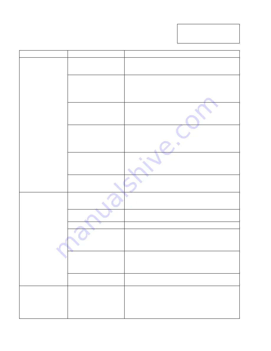
Troubleshooting
Problem Possible
Cause
Remedy
Thermostat not calling for
heat.
Check thermostat and adjust. Also, check thermostat
for accuracy; if it is a mercury switch type, it might be
off level.
No power to furnace.
Check furnace switch, main electrical panel furnace
fuse or circuit breaker. Also look for any other hand
operated switch, such as an old poorly located furnace
switch, which was not removed during furnace
replacement.
Thermostat faulty.
Check reset button on protector relay. Remove
thermostat wires from protector relay terminals T T.
Place a jumper across T T. If furnace starts, replace
thermostat, thermostat sub-base (if equipped), or both.
Protector relay faulty.
Check reset button on protector relay. Remove
thermostat wires from protector relay terminals T T.
Check for 24v across T T. If no voltage is present,
check for 115v to protector relay. If 115v is present,
replace protector relay.
Photo Cell wiring shorted
or room light leaking into
into photo cell
compartment
Check photo cell (cad cell) wiring for short circuits.
Also, check for room light leaking into cad cell
compartment. Repair light leak if necessary.
Furnace will not start.
Open safety switch.
Check for open limit or auxiliary limit, open door switch
(if equipped). Also, check internal wiring connections;
loose connectors, etc.
No fuel oil.
Check fuel oil supply. Check that all hand operated all
fuel oil valves are in the open position. Fill oil storage
tank if necessary.
Clogged nozzle.
Replace nozzle with high quality replacement. Use
rating plate or Tables in Appendix A as a guide.
Clogged oil filter.
Replace oil tank filter or in-line filter if used.
Low oil pump pressure.
Connect pressure gauge to oil pump. Adjust pump
pressure, or replace oil pump if necessary. Ensure that
erratic pressure readings are not caused by defective
fuel oil line.
Air getting into fuel oil
lines, or fuel oil line dirty,
clogged, or in some
manner defective.
Check fuel oil lines. Replace any compression fittings
found with high quality flared fittings. Check for any
signs of oil leaks. Any oil leak is a potential source of air
or contaminants.
Furnace will not start
without first pushing
protector relay reset
button.
(Happens on
frequent basis)
Defective burner motor.
Check burner motor. If burner motor is cutting out on
over-load, determine why. Replace if necessary.
Furnace starts, but
cuts out requiring
manually resetting
the oil protector reset
button.
Photo Cell (Cad Cell)
defective.
If cad cell is dirty, clean it. (Determine why cad cell is
getting dirty). If cad cell is poorly aimed, realign it.
NOTE: The photo cell should have a resistance of 100K
Ω
in absence of light; a maximum of 1500
Ω
in the
presence of light. Ensure that room light is not leaking
into the cad cell compartment.
Summary of Contents for O4LD-140A-16-R
Page 13: ...152B0801 13 APPENDIX B WIRING...
Page 18: ...152B0801 18 PARTS LISTS...
Page 21: ...152B0801 21...