14
GB
IMPORTANT! Always remember to open the air
vent control and the door when new wood logs
are inserted into a hot burn chamber. Let the
flames get established on the wood before the
air supply is reduced.
When the draught in the chimney is low and the
vents are closed, the gas from the firewood can
be ignited with a bang. This can cause damages
to the product as well as the immediate
environment.
7. Maintenance
Cleaning and Inspection
The insert should be inspected thoroughly and cleaned
at least once per season (possibly in combination
with the sweeping of the chimney and chimney pipes).
Ensure that all joints are tight and that the gaskets are
rightly positioned. Exchange any gaskets that are worn
or deformed. Remember that the insert must always be
cold when inspected.
Ashes
The ashes should be removed at regular intervals.
Be aware that the ashes can contain hot ember even
several days after the fire is finished. Use a container
of non-combustible material to remove the ashes. It is
recommended to leave a layer of ashes in the bottom
as this further insulates the burn chamber. Take care
with the insulation plates when the ashes are removed,
particularly when using an ash shovel, so as not to
damage them.
Thermotte™plates
These insulating plates (FIG 12) in the burn chamber
contribute to a high combustion temperature, which
leads to cleaner combustion of the wood and a higher
rate of efficiency. Any fissures in the plates will not
reduce their insulation efficiency. If new plates are
needed, contact your dealer.
In case the plates need to be replaced, lift the smoke
baffle (A) in order to remove the side plates.
A.
Smoke baffle
B.
Left side plate - front
C.
Left side plate - back
D.
Right side plate - front
E.
Right side plate - back
F.
Back plate
G.
Log-stopper
H.
Left bottom plate
I.
Right bottom plate
Please note: Wood logs that are too long can cause
additional strain and crack the plates, due to the tension
created between the side plates.
Please also note that the Thermotte plates may release
coloured dust when touched. Avoid touching any cast
iron parts with dust on your fingers. Any visible dust
on cast iron can be brushed off with the glove that is
included.
Door and Glass
Should there be any soot on the glass it may be
necessary to clean it. Use dedicated glass cleaner,
as other detergents may damage the glass. (NB! Be
careful, even dedicated glass cleaner can damage the
varnish on the door frame). A good advice for cleaning
the glass is to use a damp cloth or kitchen roll paper
and apply some ash from the burn chamber. Rub
around the ash on the glass and finish off with a piece
of clean and damp kitchen roll paper. NB! Only clean
when the glass is cold.
Check regularly that the transition between the glass
and the door is completely tight. Possibly tighten the
screws that hold the glass in place - but not too hard, as
this can cause the glass to crack.
Periodically, it may be necessary to change the gaskets
on the door to ensure that the burn chamber is air tight
and working optimally. These gaskets can be bought as
a set, usually including ceramic glue.
Should it be necessary to unhook the door/doors,
unscrew the lid (FIG 8) above the air vent control. The
lid is fastened underneath with 3 screws / Allen screws.
When the lid is removed, the door/doors are free to
unhook.
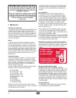
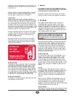
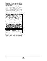
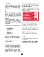
Refractory glass should
be disposed of as resid-
ual waste, together with
pottery and porcelain
REFRACTORY
GLASS CANNOT
BE RECYCLED
Recycling of the refractory glass
Refractory glass cannot be recycled. Old glass,
breakage or otherwise unusable refractory glass, must
be discarded as residual waste. Refractory glass has a
higher melting temperature, and can therefore not be
recycled together with glass. In case it would be mixed
with ordinary glass, it would damage the raw material
and could, in worst case end the recycling of glass. It is
an important contribution to the environment to ensure
that refractory glass does not end up with the recycling
of ordinary glass.
Packaging Recycle
The packaging accompanying the product should be
recycled according to national regulations.
Summary of Contents for CC-RIO00-100 Ronda
Page 38: ...38 2000 600 641 1240 336 Ronda mm Ronda air 625 135 140 ...
Page 41: ...41 X FIG 3 FIG 4 ...
Page 42: ...42 FIG 5A FIG 6 FIG 7 FIG 5B FIG 8 FIG 9A FIG 9B ...
Page 43: ...43 FIG 10 FIG 11A FIG 11B FIG 12 G H F I ...
Page 45: ...45 FIG 14 FIG 15 FIG 13 124 mm 2 1 3 FIG 16 2 165 FIG 15b ...
Page 46: ...46 FIG 18 FIG 19 FIG 20 5 6 2 mm 641 mm 4 4 FIG 17 ...


