
19
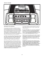
• The incline level of the treadmill
• The number of vertical feet you have climbed
• The speed of the walking belt
• Your heart rate (see step 6 on this page)
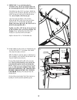
The matrix offers several display tabs. Press the
increase and decrease button next to the Enter
button until the desired tab is shown.
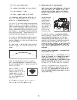
The Incline tab will show a profile of the incline set-
tings of the workout. A new segment will appear at
the end of each minute. The Speed tab will show a
profile of the speed settings of the workout. The My
Trail tab will show a track that represents 1/4 mile
(400 meters). As you exercise, the white rectangle
will show your progress. The My Trail tab will also
show the number of laps you are completing.
The Calorie tab will show the approximate amount
of calories you have burned. The height of each
segment represents the amount of calories burned
during that segment.
As you exercise, the workout intensity level bar will
indicate the approximate intensity level of your ex-
ercise.
Press the Home button to return to the default
menu (see THE INFORMATION MODE on page
23 to set the default menu). If necessary, press the
Home button again.
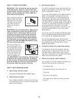
When a wireless iFit Live
module is connected, the
wireless symbol at the top of
the display will show the
strength of your wireless sig-
nal. Four arcs indicate full
signal strength.
To reset the displays, press the Stop button, re-
move the key, and then reinsert the key.
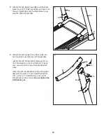
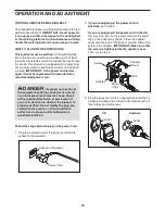
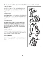
6. Measure your heart rate if desired.
Note: If you use the handgrip pulse sensor and
the chest pulse sensor at the same time, the
console will not display your heart rate accu-
rately.
For information on the chest pulse sensor,
see page 15.
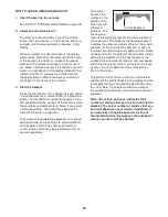
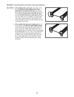
Before using the
handgrip pulse
sensor, remove
the sheets of
plastic from the
metal contacts on
the pulse bar. In
addition, make
sure that your
hands are clean.
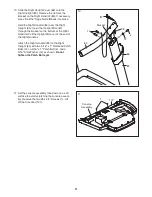
To measure your heart rate,
stand on the foot
rails
and hold the pulse bar with your palms on the
metal contacts for approximately ten seconds;
avoid moving your hands.
When your pulse is
detected, a heart symbol in the calorie display will
flash each time your heart beats, one or two
dashes will appear, and then your heart rate will be
shown.
For the most accurate heart rate read-
ing, continue to hold the contacts for about 15
seconds.
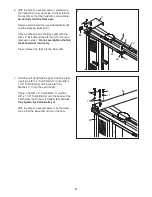
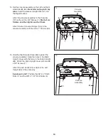
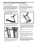
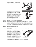
7. When you are finished exercising, remove the
key from the console.
Step onto the foot rails, press the Stop button, and
adjust the incline of the treadmill to the lowest
setting. The incline must be at the lowest set-
ting or you may damage the treadmill when you
fold it to the storage position.
Next, remove the
key from the console and put it in a secure place.
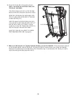
When you are finished using the treadmill, press
the power switch into the off position and unplug
the power cord.
IMPORTANT: If you do not do
this, the treadmillʼs electrical components may
wear prematurely.
Contacts