NordicTrack NETL99810.0 User Manual Download Page 15

15

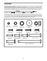
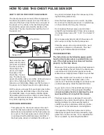
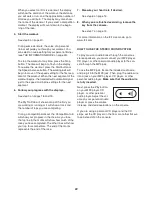
HOW TO PUT ON THE CHEST PULSE SENSOR

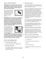
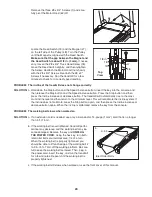
The chest pulse sensor consists of two components:

the chest strap and the sensor unit. Insert the tab on

one end of the chest strap into the hole in one end of

the sensor unit, as shown in the inset drawing. Press

the end of the sensor unit under the buckle on the

chest strap. The tab should be flush with the front of

the sensor unit.

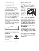
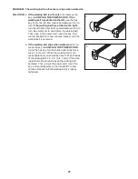
Next, wrap the chest

pulse sensor around

your chest and attach

the other end of the

chest strap to the

sensor unit. Adjust

the length of the

chest strap, if neces-

sary. The chest pulse

sensor should be under your clothes, tight against your

skin, and as high under the pectoral muscles or

breasts as is comfortable. Make sure that the logo on

the sensor unit is facing forward and is right-side-up.

Pull the sensor unit away from your body a few inches

and locate the two electrode areas on the inner side

(the electrode areas are covered by shallow ridges).

Using saline solution such as saliva or contact lens so-

lution, wet both electrode areas. Return the sensor unit

to a position against your chest.

CARE AND MAINTENANCE

• Thoroughly dry the chest pulse sensor after each

use. The chest pulse sensor is activated when the

electrode areas are wetted and the chest pulse sen-

sor is put on; the chest pulse sensor shuts off when

it is removed and the electrode areas are dried. If

the chest pulse sensor is not dried after each use, it

may remain activated longer than necessary, drain-

ing the battery prematurely.

• Store the chest pulse sensor in a warm, dry place.

Do not store the chest pulse sensor in a plastic bag

or other container that may trap moisture.

• Do not expose the chest pulse sensor to direct

sunlight for extended periods of time; do not expose

it to temperatures above 122° F (50° C) or below 14°

F (-10° C).

• Do not excessively bend or stretch the sensor unit

when using or storing the chest pulse sensor.

• Clean the sensor unit using a damp cloth—never

use alcohol, abrasives, or chemicals. The chest

strap may be hand washed and air dried.
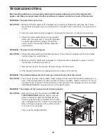
TROUBLESHOOTING

The instructions on the following pages explain

how the chest pulse sensor is used with the con-

sole. If the chest pulse sensor does not function

properly, try the steps below.

• Make sure that you are wearing the chest pulse sen-

sor as described at the left. Note: If the chest pulse

sensor does not function when positioned as de-

scribed, move it slightly lower or higher on your chest.

• Use saline solution such as saliva or contact lens

solution to wet the two electrode areas on the

sensor unit. If heart rate readings do not appear until

you begin perspiring, rewet the electrode areas.

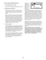
• As you walk or run on the treadmill, position your-

self near the center of the walking belt.

For the

console to display heart rate readings, the user

must be within armʼs length of the console.

• The chest pulse sensor is designed to work with

people who have normal heart rhythms. Heart rate

reading problems may be caused by medical

conditions such as premature ventricular contrac-

tions (pvcs), tachycardia bursts, and arrhythmia.

• The operation of the chest pulse sensor can be

affected by magnetic interference caused by high

power lines or other sources. If it is suspected that

this is a problem, try relocating the treadmill.

Chest Strap

Tabs

Sensor Unit

Tab

Sensor

Unit

Buckle

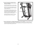
HOW TO USE THE CHEST PULSE SENSOR

Summary of Contents for NETL99810.0

Page 1: ...is manual for future reference QUESTIONS If you have questions or if there are missing parts please contact us UK Call 08457 089 009 From Ireland 053 92 36102 Website www iconsupport eu E mail csuk ic...

Page 2: ...ST 30 EXPLODED DRAWING 32 ORDERING REPLACEMENT PARTS Back Cover RECYCLING INFORMATION Back Cover This drawing shows the locations of the warning decals If a decal is missing or il legible call the tel...

Page 3: ...ecting the power cord see page 16 plug the power cord into an earthed cir cuit No other appliance should be on the same circuit When replacing the fuse in the power cord adapter insert an ASTA approve...

Page 4: ...2 Never insert any object into any opening on the treadmill 23 Inspect and properly tighten all parts of the treadmill regularly 24 DANGER Always unplug the power cord immediately after use before cle...

Page 5: ...before using the treadmill If you have questions after read ing this manual please see the front cover of this man ual To help us assist you please note the product model number and serial number bef...

Page 6: ...ey and your own Phillips screwdriver adjustable wrench needlenose pliers and scissors Use the drawings below to identify the assembly hardware The number in parentheses below each drawing is the key n...

Page 7: ...he tie to pull the Upright Wire out of the hole Attach two Base Feet 90 to the Base 95 in the locations shown with two 8 x 1 Tek Screws 5 and two Base Foot Spacers 94 Then attach the other two Base Fe...

Page 8: ...1 3 7 5 4 Identify the Right Upright 85 which is marked with a Right sticker Hold the Right Upright near the Base 95 as shown See the inset drawing Tie the wire tie in the Right Upright 85 securely ar...

Page 9: ...d person tip the tread mill so that the Base 95 is flat on the floor 84 7 95 11 11 3 7 9 6 With the help of a second person carefully tip the treadmill onto its right side Partially fold the Frame 55...

Page 10: ...Nut 38 back into place Attach the Left Handrail 82 to the Left Upright 84 with two 5 16 x 1 Flat Head Patch Bolts 14 a 5 16 x 1 Patch Bolt 4 and a 5 16 Star Washer 13 as shown Do not tighten the Patch...

Page 11: ...om of the Right Handrail Pull the Upright Wire out of the end of the Right Handrail Attach the Right Handrail 83 to the Right Upright 85 with two 5 16 x 1 Flat Head Patch Bolts 14 a 5 16 x 1 Patch Bol...

Page 12: ...the Console Ground Wires 52 Console Assembly 13 Console Wire Wire Tie Ground Wires 83 87 4 52 87 Console Wire 12 IMPORTANT To avoid damaging the Crossbar 107 do not use power tools and do not overtigh...

Page 13: ...3 8 x 4 Patch Bolts 7 and the 3 8 x 1 1 2 Patch Bolts 3 15 85 84 1 1 80 86 Console Assembly 14 Set the console assembly on the Left and Right Handrails 82 83 Be careful not to pinch any wires Insert...

Page 14: ...olt 8 and a 3 8 Nut 10 Note It may be necessary to move the Frame back and forth to align the Storage Latch with the bracket Lower the Frame 55 see HOW TO LOWER THE TREADMILL FOR USE on page 24 16 17...

Page 15: ...sensor in a plastic bag or other container that may trap moisture Do not expose the chest pulse sensor to direct sunlight for extended periods of time do not expose it to temperatures above 122 F 50 C...

Page 16: ...eadmill 2 If you are plugging in the power cord in Australia go to step 3 If you are plugging in the power cord in the UK first press the pins on the power cord into the metal clips in the adapter as...

Page 17: ...orkout re sults race against other runners and access many other features To purchase an iFit Live module at any time go to www iFit com or call the telephone number on the front cover of this manual...

Page 18: ...u are not connected to iFit Live the manual mode will be selected automatically 3 Start the walking belt To start the walking belt press the Start button the Speed increase button or one of the Quick...

Page 19: ...strength To reset the displays press the Stop button re move the key and then reinsert the key 6 Measure your heart rate if desired Note If you use the handgrip pulse sensor and the chest pulse sensor...

Page 20: ...etting are programmed for each segment Note The same speed setting and or incline setting may be programmed for con secutive segments During the workout the profiles on the speed and in cline tabs wil...

Page 21: ...into the console To use an iFit Live workout insert the iFit Live module into the console To purchase an iFit Live module at any time go to www iFit com or call the telephone number on the front cove...

Page 22: ...track and the number of laps you are completing During a competition workout the Competition tab will show your progress in the race As you race the top line in the matrix will show how much of the r...

Page 23: ...buttons will not function If the demo mode is turned on the word ON will appear in the matrix To turn on or turn off the demo mode press the Enter button or the Speed de crease button Press the decrea...

Page 24: ...latch knob is locked in the storage position Moving the tread mill may require two people 1 Hold the frame and one of the handrails and place one foot against a wheel 2 Pull back on the handrail unti...

Page 25: ...sure that the power cord is plugged in If the power cord is plugged in unplug it wait for five minutes and then plug it back in c Remove the key from the console Reinsert the key into the console d If...

Page 26: ...line level and then return to the minimum level This will recalibrate the incline system If the incline does not calibrate press the Stop button again and then press the Incline increase or decrease b...

Page 27: ...hen plug in the power cord insert the key and run the treadmill for a few minutes Repeat until the walking belt is centered b If the walking belt slips when walked on first re move the key and UNPLUG...

Page 28: ...our goal is to strengthen your cardiovascular system you must perform aerobic exer cise which is activity that requires large amounts of oxygen for prolonged periods of time For aerobic ex ercise adju...

Page 29: ...les Stretch With one leg in front of the other reach forward and place your hands against a wall Keep your back leg straight and your back foot flat on the floor Bend your front leg lean forward and m...

Page 30: ...38 2 5 16 Cage Nut 39 2 Foot Rail Decal 40 1 Left Foot Rail 41 1 Latch Warning Decal 42 2 Platform Cushion 43 2 Belt Guide 44 1 Walking Platform 45 2 Frame Cap 46 2 Frame Spacer 47 1 Magnet 48 1 Front...

Page 31: ...1 Access Door 109 1 Electronic Bracket 110 1 Filter 111 1 Transformer 112 2 Motor Bushing 113 1 Motor Isolator 114 1 Power Cord Adapter 115 1 Chest Pulse Strap 116 4 8 x 1 2 Module Screw User s Manual...

Page 32: ...32 32 43 43 30 45 30 30 30 39 40 36 36 36 47 45 46 36 44 41 49 48 54 39 60 55 56 56 46 58 59 61 57 18 42 10 24 23 18 18 18 18 18 18 18 19 19 20 24 30 30 30 30 28 42 8 10 10 8 6 32 EXPLODED DRAWING A...

Page 33: ...15 15 15 15 74 18 73 37 37 37 1 1 1 22 22 28 62 64 76 75 65 28 31 67 66 63 77 79 78 68 28 28 72 111 109 110 28 28 28 28 69 114 71 70 112 113 EXPLODED DRAWING B Model No NETL99810 0 R0810A 33...

Page 34: ...5 96 96 8 7 11 7 11 27 35 89 89 85 95 92 92 94 90 5 94 25 26 35 35 97 98 87 10 10 8 93 87 86 83 82 81 81 80 38 38 1 1 14 14 4 4 13 13 9 9 27 35 84 3 3 11 11 88 91 34 EXPLODED DRAWING C Model No NETL99...

Page 35: ...53 1 108 103 101 12 107 1 2 52 29 104 102 106 1 1 1 1 1 12 2 1 1 1 1 1 1 1 100 17 105 105 50 53 115 16 99 1 1 1 1 116 116 35 EXPLODED DRAWING D Model No NETL99810 0 R0810A...

Page 36: ...part s see the PART LIST and the EXPLODED DRAWING near the end of this manual RECYCLING INFORMATION This electronic product must not be disposed of in municipal waste To pre serve the environment this...

Reviews: