background image


APPLIANCE 

Rev. 01 of 01/07/2019 
Translation of the original instructions in Italian 


SOLL. 

5.2


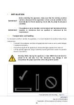
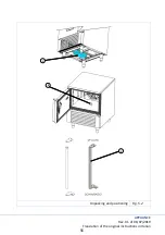
Unpacking and positioning 

Before starting installation, follow this unpacking procedure very carefully. 

1.


Place the appliance, still packed, near the place where it will be installed. To do 
this, it is advisable to use a roller trolley, avoiding dragging the appliance in order 
not to damage people or property. 

2.


When the place has been chosen, make sure there is enough space to open the 
main door. 

3.


Install the appliance in a dry, well-ventilated place, away from sources of heat (for 
example  a  radiator,  hob,  etc.)  and  in  a  place  where  it  is  not  exposed  to  direct 
sunlight. If necessary, use an insulating panel. 

4.


Insufficient ventilation at the back of the appliance increases power consumption 
and reduces the cooling efficiency. 

5.


Cut the straps and remove the cardboard packaging upwards. Do not blades, to 
avoid scratching the steel panels of the appliance. 

6.


Remove the protective box and place the appliance in the final position. 

7.


Remove the PVC film from all sides. 

8.


Remove the plastic protection from the core probe. 

9.


Place  the  plastic  condensate  collection  tray,  which  can  be  found  inside  the  cell 
when it is opened for the first time, under the technical compartment, sliding it 
into the dedicated rails (ref. Fig. 5.2). 

10.


Using the plug that can be found inside the cell when it is opened for the first time, 
close the drain hole inside the cell (ref. Fig. 5.2). 

11.


Install  the  handle  of  the  machine,  that  can  be  found  inside  the  cell  when  it  is 
opened for the first time (ref. Fig. 5.2). 

12.


Level the appliance vertically by means of the adjustable feet to ensure its stability, 
correct air circulation and condensate drainage. 

13.


Keep a minimum distance of 10 cm from the sides and the back to ensure correct 
air circulation. 

14.


After unpacking the unit, make sure that it is not damaged. Any damage must be 
reported to the dealer within 24 hours of delivery. 

15.


Wait at least two hours before activating the appliance, to allow the refrigerant 
circuit to be perfectly efficient. 

16.


Clean the inside of the appliance before using it. 


55 

Summary of Contents for 433000106

Page 1: ...Bedienungsanweisung Schnellk hler Schockfroster SKF 15 GN 1 1 PLUS Art 433000106 2019 07...

Page 2: ...20 7 5 Bildschirmseite HOME 24 7 5 1 Bildschirmseite Einstellungen 25 7 6 Men Schnellk hlen Tiefk hlen 27 7 6 1 Informationen zu den Zyklen der Schnellk hlung und Tiefk hlung 28 7 7 Men Garen bei nie...

Page 3: ...uf damit sie von den verschiedenen Bedienern eingesehen werden kann Der Hersteller lehnt jede Verantwortung und alle Garantieverpflichtungen im Falle von Personen Tier oder Sachsch den ab die sich aus...

Page 4: ...ngs und Spannungsdaten f r die Stromversorgung mit denen am Aufstellungsort bereinstimmen siehe Kap 4 Im Falle einer Funktionsst rung das Ger t ausschalten und alle Anschl sse unterbrechen Die Arbeite...

Page 5: ...e ordentliche Wartung nicht entfernt oder manipuliert werden Stecken Sie keine Werkzeuge oder K chenutensilien in die Schutzvorrichtung von elektrischen oder mechanischen Teilen Verwenden Sie keine me...

Page 6: ...es Ger ts muss von zwei oder mehr Personen durchgef hrt werden Installation und Wartung einschlie lich des Austausches des Netzkabels m ssen vom Hersteller oder einem qualifizierten Techniker unter Be...

Page 7: ...ferung von Informationen ber die f r die Stromversorgung der Maschine erforderliche elektrische Leistung und Spannung Lieferung von Informationen ber die Typologie und Menge von K ltemittel CE Kennzei...

Page 8: ...ICHTIG Der Hersteller lehnt jede Verantwortung ab die sich aus der nicht bestimmungsgem en Verwendung des Produkts ergibt siehe Kap 6 und beh lt sich au erdem das Recht vor nderungen an seinen Produkt...

Page 9: ...stu ng 5570 10 45 C Volt 400 Nr Bleche GN 1 1 H40 H65 15 GN 1 1 H20 EN 60x40 30 Verfl ssigung Luft Ph 3 N Schnellk hlen 63 kg K ltemittelgas R404A Hz 50 Tiefk hlen 47 kg Au enabm mm 750 x 799 5 x 2002...

Page 10: ...orrekten Transport und die anschlie ende Handhabung des Ger tes wird empfohlen die folgenden Anweisungen sorgf ltig zu befolgen 1 Das Ger t unter Verwendung von solchen Mitteln und Vorsichtsma nahmen...

Page 11: ...ung entfernen und das Ger t in seiner endg ltigen Position aufstellen 7 Die PVC Schutzfolie von allen Seiten entfernen 8 Den Kunststoffschutz von der Kerntemperatursonde entfernen 9 Die Wanne zur Kond...

Page 12: ...GER T Rev 01 des 01 07 2019 bersetzung der Originalanleitungen SOLL Auspacken und Positionierung Abb 5 2 1 2 3 12...

Page 13: ...Anlage f r die zu installierende elektrische Leistung ausgelegt ist 4 Im Falle eines Austausches sind elektrische Kabel zu verwenden deren Eigenschaften nicht unter denen der urspr nglichen Kabel lie...

Page 14: ...ist das technische Personal zur berpr fung der korrekten Installation verpflichtet 1 Die korrekte Funktionsweise des elektrischen Anschlusses berpr fen 2 Die korrekte Funktionsweise des hydraulischen...

Page 15: ...lt als unsachgem und potenziell gef hrlich Der Hersteller lehnt jegliche Verantwortung und Garantieverpflichtung f r Sch den am Ger t an Personen und Eigentum ab die auf Folgendes zur ckzuf hren sind...

Page 16: ...01 des 01 07 2019 bersetzung der Originalanleitungen SOLL 7 BETRIEB 7 1 Einschalten Das folgende Diagramm zeigt die Vorg nge die bei der Inbetriebnahme des Ger tes durchzuf hren sind Start des Ger ts...

Page 17: ...eite Wahl der Sprache Wahl der Sprache Abb 7 2 Beim Einschalten des Ger ts ist der erste auszuf hrende Vorgang die Auswahl der Sprache Die Taste mit der Fahne der gew nschten Sprache anw hlen die Ausw...

Page 18: ...R VERWENDEN SI START UM TITOLO 1 DEM TEXT ZUZUWEISEN DER HIER ANGEZEIGT SOLL 7 3 Bildschirmseite Wi Fi Verbindung Wi Fi Verbindung Abb 7 3 Nach der Wahl der Sprache ist es erforderlich sich mit einem...

Page 19: ...rdparameter mit der entsprechenden Bildlaufleiste zu ndern Um die Zyklusphasen zu ndern die Taste Erweitert dr cken Die erscheinende Bildschirmseite erlaubt die Phase ber das Kontrollk stchen zu aktiv...

Page 20: ...die Seite der Einstellungen siehe Abs 7 5 1 Bildschirmseite Einstellungen Taste Alarme Ihr Druck erlaubt den Zugriff auf die Seite der Visualisierungen der Alarme des Ger ts wenn die Taste gelb ist D...

Page 21: ...te zur nderung der aktivierten Phase des Zyklus Taste Kontrollk stchen Ihr Druck aktiviert die betreffende Phase Ikone Zellentemperatur Grafische Darstellung der Temperatur in der Zelle Ikone Vork hlu...

Page 22: ...s der Kerntemperatursonde erm glicht Das Schreiben des Namens erfolgt ber ein alphanumerisches Tastenfeld das durch den Druck des Felds Hinzuf gen erscheint Taste Rezept speichern Ihr Druck erlaubt de...

Page 23: ...Daten zu best tigen Taste L schen Ihr Druck erlaubt die eingestellten Daten zu l schen und zur vorherigen Bildschirmseite zur ckzukehren Taste Soft Ihr Druck erlaubt den Zyklus in der Ausf hrung Soft...

Page 24: ...VERWENDEN SIE DIE REGISTERKARTE ZUZUWEISE SOLL 7 5 Bildschirmseite HOME HOME Abb 7 5 Auf der Bildschirmseite HOME ist es m glich die folgend aufgelisteten Zyklen zu w hlen Schnellk hlen Tiefk hlen Gar...

Page 25: ...erlaubt den Zugriff auf die Bildschirmseite zur Wahl der Sprache siehe Abs 7 2 Bildschirmseite Wahl der Sprache Taste WI FI Ihr Druck erlaubt den Zugriff auf die Bildschirmseite zur WI FI Verbindung s...

Page 26: ...tellten Zyklus durch Druck der Taste Schnellstart auf der Bildschirmseite HOME auszuf hren siehe Abs 7 5 Bildschirmseite HOME Um den Zyklus erneut mit Schnellstart einzustellen muss die Taste gedr ckt...

Page 27: ...ich Um das Lesen des Handbuchs zu erleichtern wird nur das Men Schnellk hlen behandelt Zum Zugriff auf das Men Schnellk hlen Tiefk hlen die bez gliche Taste auf der Bildschirmseite HOME dr cken siehe...

Page 28: ...e Startbildschirmseite in vereinfachter Form Bez A Abb 7 8 Wenn Daten oder Elemente auf den Bildschirmseiten grau erscheinen bedeutet dies dass sie nicht aktiviert oder nicht ver nderbar sind Bez B Ab...

Page 29: ...Zugriff auf das Men Garen bei niedriger Temperatur die bez gliche Taste auf der Bildschirmseite HOME dr cken siehe Abs 7 5 Bildschirmseite HOME Dieses Men besteht aus einem manuellen Zyklus und aus ei...

Page 30: ...lentemperatur und die Sondentemperatur ndern kann und die Bel ftung und die Erhaltung standardm ig eingestellt sind Bez A Abb 7 10 Wenn Daten oder Elemente auf den Bildschirmseiten grau erscheinen bed...

Page 31: ...ionsweise des Zyklus werden ber Pop up visualisiert F r den Zugriff auf das Men der Sonderzyklen die bez gliche Taste auf der Bildschirmseite HOME dr cken siehe Abs 7 5 Bildschirmseite HOME Dieses Men...

Page 32: ...erte Zyklus vorgesehen Die Desinfektion von Fisch ist ein automatischer Zyklus und sieht keine erweiterten nderungen vor Au erdem kann der Benutzer w hlen ob er am Ende des Zyklus ein automatisches Au...

Page 33: ...dert werden k nnen Men Zyklen Zelle Abb 7 12 7 9 1 Informationen zu den Zyklen Zelle Folgend eine Liste n tzlicher Informationen f r den Betrieb der Zyklen Die Zyklen Zelle sind automatisch und sehen...

Page 34: ...s Problem weiterhin besteht Kontakt mit dem technischen Kundendienst aufnehmen ACHTUNG EINGRIFF DES HOCHDRUCKW CHTERS DIE MASCHINE ABSCHALTEN ES IST ERFORDERLICH DEN SICHERHEITSDRUCKW CHTER ZUR CKZUSE...

Page 35: ...worden sein ACHTUNG BERM SSIGE DAUER DES BLACKOUT DAS PRODUKT PR FEN Die Dauer des Stromausfalls war zu lang die Produkte berpr fen die Qualit t der Lebensmittel k nnte beeintr chtigt worden sein ACHT...

Page 36: ...jeden Fall nicht mehr als 40 mm um den Luftstrom der das Produkt umgibt nicht zu behindern Der Mindestabstand von einem Blech zum anderen betr gt 2 cm NICHT ZU EMPFEHLEN VORZUZIEHEN Nutzen Sie die ges...

Page 37: ...nem weichen Tuch und warmem Wasser reinigen und dann wieder in die Zelle zur ckstellen Positionierung der Sonde Abb 10 1 Achtung Lassen Sie die Kerntemperatursonde nicht au erhalb der T re des Schnell...

Page 38: ...Sonde nicht ziehen um sie aus dem Produkt zu entfernen Die Sonde nicht mit einer Flamme erw rmen Die Produkte wurden mit u erster Sorgfalt und Aufmerksamkeit geplant und erstellt um dem Benutzer die...

Page 39: ...chen Kundendienst Im Falle eines l ngeren Stillstands ist Folgendes angemessen 1 Die Ausf hrung einer sorgf ltigen Reinigung der Innen und Au enseite 2 Der Schutz der u eren Oberfl chen mit spezifisch...

Page 40: ...en Verwendung abtrennen Achtung Vor dem Gebrauch die Unversehrtheit des Ger ts kontrollieren und eine sorgf ltige und komplette Reinigung des Ger ts ausf hren 11 5 Entleerung Kondensatsammelwanne F r...

Page 41: ...enen Phasen des Herstellungszyklus durchgef hrt Alle bei der Konstruktion verwendeten Materialien sind f r die Verwendung mit Lebensmitteln garantiert Die im K ltekreislauf verwendeten Gase sind die i...

Page 42: ...Wiederverwertung Entsorgung zu veranlassen Eine angemessene getrennte Sammlung f r das anschlie ende Recycling die Behandlung und die umweltgerechte Entsorgung von Altger ten tr gt dazu bei m gliche n...

Page 43: ...rdnung Nr 1935 2004 entwickelt Dieses Ger t wurde gem Folgendem geplant hergestellt und vermarktet Den Sicherheitsanforderungen der Niederspannungsrichtlinie 2014 35 EU Den Schutzanforderungen der Ric...

Page 44: ...nzten Mengen in unseren Produkten erlaubt Blei Quecksilber Cadmium Sechswertiges Chrom Polybromierte Biphenyle PBB Polybromierte Diphenylether PBDE WEITERE INFORMATIONEN In Anbetracht des oben Genannt...

Page 45: ...User Manual Blast Chiller SKF 15 GN 1 1 PLUS Art 433000106 2019 07...

Page 46: ...iption of keys 64 7 5 HOME screen 68 7 5 1 Settings screen 69 7 6 Blast chilling Deep freezing menu 71 7 6 1 Information on the Blast chilling and Deep freezing cycles 72 7 7 Low temperature baking me...

Page 47: ...ng the product Keep this booklet carefully for future reference The manufacturer declines all liability and any warranty obligations if damage is caused to people animals or property because the advic...

Page 48: ...power supply indicated on the CE plate Fig 4 1 correspond to those available in the place where it will be installed see chapter 4 In the event of malfunction turn the appliance off and disconnect it...

Page 49: ...otections of electrical or mechanical parts Do not use mechanical electronic or chemical devices to accelerate the defrosting process other than those recommended by the manufacturer Do not use or ins...

Page 50: ...maintenance including replacing the power cord must be performed by the manufacturer or by a specialised technician in accordance with local safety regulations To avoid dangers do not repair or repla...

Page 51: ...ion thanks to the model code and serial number Provide information on the electric power and voltage required to power the machine Provide information on the type and amount of refrigerant gas CE plat...

Page 52: ...OLL Position of CE plate Fig 4 2 IMPORTANT The manufacturer declines all liability arising from unforeseen uses of the product see chapter 6 and also reserves the right to make changes to the products...

Page 53: ...5 C Volts 400 No Trays GN 1 1 H40 H65 15 GN 1 1 H20 EN 60x40 30 Condensation Air Ph 3 N Blast chilling 63 kg Coolant gas R404A Hz 50 Deep freezing 47 kg External dimensions mm 750 x 799 5 x 2002 MAX r...

Page 54: ...by the manufacturer 5 1 Transportation and handling To transport and then handle the appliance it is recommended to carefully follow these instructions 1 Transport the appliance carefully using approp...

Page 55: ...otective box and place the appliance in the final position 7 Remove the PVC film from all sides 8 Remove the plastic protection from the core probe 9 Place the plastic condensate collection tray which...

Page 56: ...APPLIANCE Rev 01 of 01 07 2019 Translation of the original instructions in Italian FEHLER VERWENDEN SI START UM TITOLO 1 DEM TEXT ZUZUWEISEN DER HIER SOLL Unpacking and positioning Fig 5 2 1 2 3 56...

Page 57: ...d 2 Make sure that the electrical system complies with the regulations in force 3 Make sure that the system is dimensioned to the electrical power to be installed 4 In case of replacement use electric...

Page 58: ...sitioning and connecting the appliance the technician must make sure that it has been installed correctly 1 Check that the electrical connection works correctly 2 Check that the hydraulic connection w...

Page 59: ...nsidered improper and potentially dangerous The manufacturer declines all liability and all warranty obligations in the event of damage to the appliance to people or to property attributable to Incorr...

Page 60: ...1 07 2019 Translation of the original instructions in Italian ZUZUWEISEN SOLL 7 OPERATION 7 1 Ignition The following diagram shows the operations to be performed when the appliance is started Applianc...

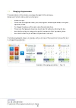
Page 61: ...ER ANGEZEIGT WERDEN SOLL 7 2 Language selection screen Language selection Fig 7 2 When the appliance is turned on the first thing to do is select the language Select the key with the flag of the langu...

Page 62: ...al instructions in Italian FEHLER VERWENDEN SIE DIE REGISTERKARTE START UM TITOLO 1 SOLL 7 3 Wi Fi connection screen Wi Fi connection Fig 7 3 After selecting the language it is necessary to connect to...

Page 63: ...change the standard parameters using the special scroll bar To change the phases of the cycle press the Advanced key The screen that appears allows you to activate the phase by checking the box Press...

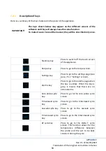
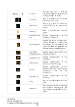
Page 64: ...ss to go to the recipe screen Settings key Press to go to the settings page see para 7 5 1 Settings screen Alarms key Press to go to the alarms page when the key is yellow When the key is grey it mean...

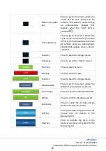
Page 65: ...representation of the pre cooling temperature Setting the pre cooling involves starting the cycle only after the appliance has reached the selected temperature Core probe temperature icon Graphic rep...

Page 66: ...at appears when a field is selected Save key Press to save the changes made Home key Press to go to the Home screen Start key Press to start the cycle Stop key Press to stop the cycle Save key Press t...

Page 67: ...ranslation of the original instructions in Italian FEHLER VERWENDEN SIE DIE REGISTERKARTE SOLL Baking level keys Press to select the baking level Keys not featured in the manual cycle In some baking t...

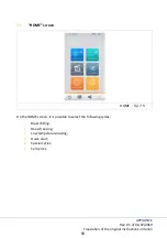
Page 68: ...ions in Italian FEHLER VERWENDEN SI START UM TITOLO 1 ZUZUWEISEN DER HIER SOLL 7 5 HOME screen HOME Fig 7 5 On the HOME screen it is possible to select the following cycles Blast chilling Deep freezin...

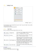
Page 69: ...language selection screen see para 7 2 Language selection screen WI FI key Press to go to the Wi Fi connection screen see para 7 3 Wi Fi connection screen HACCP Register key Press to go to the next me...

Page 70: ...le by pressing the quick start key on the HOME screen see para 7 5 HOME screen To reset the cycle in quick start press the key Programmed key Press to go to the menu where the defrost and cell sanitis...

Page 71: ...edit and cycle start procedures are the same To make the manual easier to read only the Blast chilling menu will be described To access the Blast chilling Deep freezing menu press the respective key...

Page 72: ...time based cycle cascade cycle and timer based cycle to view the start screen in a simplified form Ref A Fig 7 8 When some data or an element is grey it means that it is not enabled Ref B Fig 7 8 A cy...

Page 73: ...ycle operation is displayed via pop up To access the Low temperature baking menu press the respective key on the HOME screen see para 7 5 HOME screen This menu consists of a manual cycle and a series...

Page 74: ...simplified form where the user can change the cell temperature and the probe temperature ventilation and maintenance are set by default Ref A Fig 7 10 When some data or an element is grey it means tha...

Page 75: ...ANT Any important information for optimal cycle operation is displayed via pop up To access the Special cycles menu press the respective key on the HOME screen see para 7 5 HOME screen This menu consi...

Page 76: ...obe cycle and the time based cycle are included Fish sanitisation is an automatic cycle and does not feature advanced settings Also the user can choose whether or not to perform automatic thawing at t...

Page 77: ...ds Cell cycles menu Fig 7 12 7 9 1 Information on the cell cycles Below is a list of useful information concerning the cycles The cell cycles are automatic and feature no advanced settings During the...

Page 78: ...NING HIGH PRESSURE PRESSURE SWITCH TRIGGERED SWITCH OFF THE MACHINE IT IS NECESSARY TO RESTORE THE SAFETY PRESSURE SWITCH IF THE MALFUNCTION PERSISTS CONTACT TECHNICAL SUPPORT A Check that there are n...

Page 79: ...HE PRODUCT The duration of the blackout was excessive check the products the quality of the food may have been compromised WARNING THE CHAMBER TEMPERATURE IS DROPPING TOO SLOWLY CHECK THE PRODUCT The...

Page 80: ...epth and in any case not deeper that 40 mm in order not to obstruct the airflow hitting the product The minimum space to keep between one tray and the other is 2 cm NOT RECOMMENDED PREFERABLE Use the...

Page 81: ...e blast chiller clean it using a soft cloth and warm water then put it back in the cell Probe positioning Fig 10 1 Warning Do not leave the core probe handing outside the blast chiller door It is reco...

Page 82: ...isconnect it Do not pull the probe cable to pull it out of the product Do not heat the probe with a flame The products are designed and made with extreme care and attention to provide the user with th...

Page 83: ...stance In case of a long period of inactivity it is advisable to 1 Thoroughly clean the appliance both inside and out 2 Protect the external surfaces with specific oil based products for steel and lea...

Page 84: ...e power plug until it is used again Warning Before using it again make sure that the appliance is intact and clean it carefully and completely 11 5 Emptying the condensate collection tray For a correc...

Page 85: ...reful inspections are performed on all products during the various phases of the construction cycle All the materials used to built it are guaranteed for food use The gases used in the refrigerator ci...

Page 86: ...is purchased in order to recycle dispose of it correctly An efficient separate waste collection leading to the subsequent recycling of the disused appliance or disposal compatible with the environmen...

Page 87: ...designed in accordance with EC Regulation no 1935 2004 This appliance has been designed manufactured and marketed in accordance with the safety objectives of the Low Voltage directive 2014 35 EU the...

Page 88: ...prohibited or only allowed in limited quantities in our products Lead Mercury Cadmium Hexavalent chromium Polybrominated Biphenyls PBB Polybrominated Diphenyl Ethers PBDE FURTHER INFORMATION In view...

Reviews: