NOLO CV1 PRO Instructions Manual Download Page 6

5.

开启

NOLO

设备

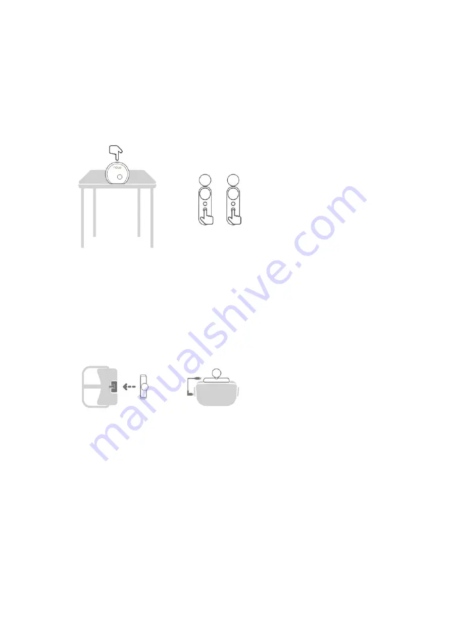
将基站放置在与肩同高的水平桌面边缘,并保持基站正面朝 外正对使用者,然后开启基站
和手柄的电源开关。

5. Turn on the NOLO Device

Place the base station on the shoulder-height table edge with the front side facing the user, and
then turn on the power switches of the base station and controllers.

6.

连接头盔定位器

NOLO

附带的头盔定位器底座粘贴在

VR+

体机上

(

注意不要遮挡电源键然后将头盔定位器

插入底座;
使用

OTG

线连接头盔定位器和

VR+

体机。

6. Connect the Headset Marker

Stick the base of the attached headset marker of NOLO to the standalone headsets (Be careful not
to cover the power key) and then insert the headset marker into the base;
Connect the headset marker and the standalone headsets through the OTG cable.

7.

建立

PC

连接

开启电脑上和

VR—

体机内的

NOLO HOME,

呆持

VR—

体机中 的

NOLO HOME

为等待连接

状态,待电脑自动扫描到一体机后,点击连接按纽。

7. Connect the PC

Run the NOLO HOME software of the computer and standalone headsets, and keep the NOLO
HOME of the standalone headsets running, and then click the button of Connect after the
standalone headsets is searched by the computer.

Summary of Contents for CV1 PRO

Page 1: ...NOLO NOLO Instructions www nolovr com getstarted For detailed instructions please visit the official website www nolovr com getstarted Package Contents X1 X2 X1 Model CV1 PRO...

Page 2: ...Positioning Base Station 1 Interactive Controller 2 Headset Marker 1 X1 X1 L X1 Power Adapter 1 Slotted Positioner Socket 1 L type Positioner Socket 1 X1 OTG X2...

Page 3: ...ble 2 1 m Data Cable 1 Slotted Positioner Socket 1 Learn More about the Device 1 2 3 4 5 6 7 Interactive Controller 1 Trigger Key 2 Pairing Key 3 Side Keys Each for the left and right sides 4 Touch Ke...

Page 4: ...Positioning Base Station Power Key Pairing Key USB Headset Marker Indicator Lamp USB Interface Pairing Key...

Page 5: ...re Preparation of PCs NOLO HOME Windows http download nolovr com Download and install the Windows version of NOLO HOME http download nolovr com 3 VR_ VR NOLO HOME 3 Software Preparation of the Standal...

Page 6: ...dset marker of NOLO to the standalone headsets Be careful not to cover the power key and then insert the headset marker into the base Connect the headset marker and the standalone headsets through the...

Page 7: ...ease refer to IV Instructions for the calibration method PC II Instructions for the PC Head Mounted Display Device 1 PC PC PC 1 Connect the PC head mounted display device Connect the PC head mounted d...

Page 8: ...eadset marker and the PC head mounted display device through the OTG cable 4 NOLO 4 Turn on the NOLO Device Place the base station on the shoulder height table edge with the front side facing the user...

Page 9: ...e station and start to enjoy the ultimate gaming experience Notes Please refer to IV Instructions for the calibration method III Instructions for Android Mobile Phone VR Note The VR glasses are needed...

Page 10: ...3 Software Preparation of the Standalone Headsets Download and install the NOLO HOME through the application market of the mobile phone Run the NOLO HOME on the mobile phone 4 OTG USB 4 Connect the H...

Page 11: ...lace the base station on the shoulder height table edge with the front side facing the user and then turn on the power switches of the base station and controllers 7 PC NOLO HOME NOLO HOME 7 Connect t...

Page 12: ...IV NOLO Instructions 1 2 3 NOLO Placement Requirements for the Positioning Base Station 1 The base station is suggested to place at the shoulder height position 2 The base station should be ensured o...

Page 13: ...of the two controllers twice respectively to complete the calibration of the positive direction Correct Operations Wrong Operations Keep your arms forward Keep your hands together With your eyes to th...

Page 14: ...f the equipment mentioned above is running please turn off the interference equipment or change the environment 3 Try to avoid the presence of the reflection plane like mirror in the environment If vi...

Page 15: ...reen 3 3 Respectively long press the Pairing Key of the two interactive controllers as shown till the controller vibrates During each pairing process each controller can only be paired once Please do...

Page 16: ...indicator lamp of two controllers and the headset marker turn to green after 3 to 5 seconds then the pairing succeeds if turn to red then the pairing fails and please re pair NOLO NOLO Device Status...

Page 17: ...sure enough space to stretch your arms when using the controllers Please firmly hold the controllers to avoid collision injuries or damages to surrounding people pets or objects 3 NOLO 3 Please do not...

Page 18: ...such as the pacemaker implanted cochlea and hearing aid Please consult the manufacturer of this device about its restrictions if you use any of the medical equipment 11 15 11 Please keep 15 cm at lea...

Page 19: ...ff to confirm whether it can be replaced according to the valid repair records of the warranty card If the customer service staff confirms that it can be replaced a new product of the same model and s...

Page 20: ...company will take the responsibility if the damages occur in the delivery process sent by us Damages caused by force majeure factors such as earthquake fire and lighting stoke Counterfeit and shoddy p...

Page 21: ...Hazardous and noxious substance or element Shell Circuit Board Charger Accessories Package IEC62321 This form is compiled according to the provisions of IEC 62321 O IEC62321 O refers to the content of...

Page 22: ...use period is applicable to some parts For example a different label is pasted on the battery unit module The environmental protection use period is only applicable to the prescribed operating enviro...

Page 23: ...ntact E mail Address Postcode Product Model Contact Device SN No NOLO VR NOLO VR www nolovr com Follow NOLO VR Official WeChat Contact NOLOVR Customer Service For more information please visit www nol...

Page 24: ...n radiate radio frequency energy and if not installed and used in accordance with the instructions may cause harmful interference to radio communications However there is no guarantee that interferenc...

Reviews: