4
Operation:
The Start Bar will perform a system test before every machine cycle. The test
cycle will require approximately one second to complete. Then the Ready
indicator will light and a machine cycle can be started.
In order to begin a machine cycle, both hand switches must be touched
concurrently within a half a second. The load will remain energized* until one
or both hand switches are released or the optional Reset switch is opened.
If the optional Hold switch is used, it will allow the load to remain energized
even after the hand switches are released. The Hold switch should stay closed
for the rest of the machine cycle. To end the machine cycle, the Reset switch is
opened momentarily.
Both hand switches must be released and the Reset switch must be closed
before another machine cycle can be started.
* An optional load timer can be used to limit how long the load will receive
power. The TB-2 is reset after the time cycle is completed. See parts list.
Wiring the Start Bar:
After mounting the Start Bar, remove the eight screws from the front panel. Lift
off the front panel to access the wiring terminal strip. All wiring must enter and
exit through the 3/4" hole in the back of the Start Bar. This hole will
accommodate a 3/8" liquid-tight conduit connector. The seven terminals on
the right side of the terminal strip are used for the hand switches. DO NOT
MAKE ANY CONNECTIONS TO THESE TERMINALS!
Wiring to the supply:
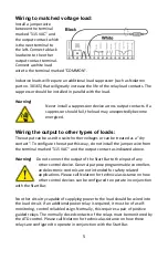
Connect a green ground wire
to the terminal identified as
"GROUND". This wire must be
connected to the main ground
terminal of the machine and
must not be fused. Connect a
black (hot) wire to the
terminal identified as "115 VAC". It is a good practice to fuse
this wire (8A max.). Connect a white (neutral) wire to the terminal identified as
"COMMON".
Summary of Contents for TB-2 Series
Page 2: ......


