background image


1


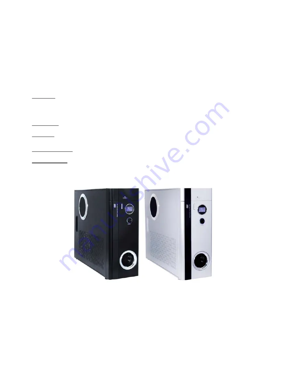
Home Theater PC Chassis 


Model: HTPC 300 BA & SA 


Color: Black & Silver 


Quick Installation Guide 


(U.S. & Canada Only) 

Version 1.0 


DISCLAIMER 

No warranty or representation, either expressed or implied, is made with respect to the content of this documentation, its quality, performance, merchantability, 
or fitness for a particular purpose. Information presented in this documentation has been carefully checked for reliability; however, no responsibility is 
assumed for inaccuracies. The information contained in this documentation is subject to change without notice. 
In no event will nMedia will be liable for direct, indirect, special, incidental, or consequential damages arising out of the use or inability to use this product or 
documentation, even if advised of the possibility of such damages. 


TRADEMARKS 

All trademarks used in this user guide are the property of their respective owners. 
 

COPYRIGHT 

© 2006 by NMEDIA SYSTEM, INC. All rights reserved. No part of this publication may be reproduced, transmitted, transcribed, stored in a retrieval system, or 
translated into any language in any form by any means without the written permission of NMEDIA SYSTEM, INC. 
 

TECHNICAL SUPPORT 

If a problem arises with your system and no solution can be obtained from this user guide, please contact your place of purchase or local dealer. 
 

REVISION HISTORY 


V 1.0 

December, 2005 


Note: 

This user guide is designed to provide the user a quick reference for chassis setup. We assume 
you need the information regarding how to assemble the system, such as Motherboard, CPU, 
RAM Memory, Hard Drive, DVD ROM, Operating System…, etc. Based on this assumption, we 
make this user guide of quick installation guide. Please follow the description step by step to 
assemble the components. If you have any question in assembling the system, you can contact 
your dealer or our technical support. 


Summary of Contents for HTPC 300 BA

Page 1: ...this user guide are the property of their respective owners COPYRIGHT 2006 by NMEDIA SYSTEM INC All rights reserved No part of this publication may be reproduced transmitted transcribed stored in a re...

Page 2: ...x 1 Air Duct Constant fresh air to CPU and avoid hot air re circulation Front Connectors Onboard headers required o USB 2 0 o IEEE 1394 o Audio Ports LCD Module Tight Cables Screws Installation Guides...

Page 3: ...priately until your case eject button can eject the tray smoothly then mark down the position and secure the DVD to the DVD rack with screws 6 Remember that installing power supply should always the l...

Page 4: ...irst find the MIC and GND pin connect the MIC GND connector fist then the SR connector must on the Pin 5 6 face the same label direction of the MIC GND connector plug the SR in same to the SL on Pin 8...

Page 5: ...ard fan connector In this case the LCD will only display fan speed no fan speed control will be available via the front knob C F SW enables you to set temp display reading format when installing the s...

Page 6: ...is Step 4 Install Power Supply 1 Take off the two brackets and install the brackets into the power supply screw holes 2 Plug in the extension cord and install the power supply by screwing the two brac...

Page 7: ...or more details CPU Temp 0 86 F 86 F up 104 F up 122 F up CPU Fan Spin Speed 70 of full speed 80 of full speed 90 of full speed 100 full speed Warning By using LCD to display CPU Temperature and contr...

Page 8: ...d adjust properly 110 230V Always unplug the power cord before inserting any add on devices Get the system checked by service personnel if below happens The power cable is damage Liquid has penetrated...

Reviews: