2 of 3
Sensor Switch 900 Northrop Road, Wallingford, CT 06492 Phone: 1-800.PASSIVE sensorswitch.com/nlight ©2014 Acuity Brands Lighting, Inc. All rights reserved 09/26/14
nPP16 Power / Relay Pack
Note 1
BLK - 120 VAC
ORN - 277 VAC (or 347 VAC if unit has 347 option)
nPP16
WHT
(neutral)
BLU
(line in)
BLU
(line out)
CAT-5e
120 VAC
OR
277 VAC
1
BLK
1
(line in)
ORN
1
(line in)
LOAD
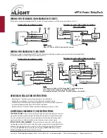
WIRING FOR STANDARD (NON-EMERGENCY) UNITS
T568B pin/pair assignment is recommended for all CAT-5e cables. For Supply Connections, use 14 AWG or larger wires rated for at least 75º C.
BUTTON
LED
RJ-45 PORTS
WHT
(neutral)
BLU
(line in)
BLU
(line out)
VIO
(low voltage dim out)
GRY
(low voltage common)
GRN
CAT-5e
nPP16 D
or
nPP16 DS
0-10 VDC
Ballast or
LED Driver
120 VAC
OR
277 VAC
1
ORN
1
(line in)
BLK
1
(line in)
Diagram for units with a dimming option
(-D or -DS suffix)
Diagram for non-dimming units
BLU
(Switched Out
)
BLU
(Emer. Feed)
BLK
Normal
3
Emergency
OPTIONAL
TEST
SWITCH
WHT w/ RED
STRIPE
(Emer. Neutral)
RED
(277VAC
Emer. Feed
2
)
{
WHT
(Normal Neutral)
{
EMERGENCY
LOAD
nPP16 ER
CAT-5e
(Normal Feed)
(sense only)
YEL
120 VAC
OR
277 VAC
1
(120VAC
Emer. Feed)
WIRING FOR EMERGENCY (-ER) UNITS
T568B pin/pair assignment is recommended for all CAT-5e cables. Unit powers itself but does not provide any bus power to other connected nLight devices.
For Supply Connections, use 14 AWG or larger wires rated for at least 75º C.
•
Mount through a ½” knockout in any junction box or luminaire. Secure with lock nut.
•
Following above wiring diagram, connect wires to line voltage feed(s), neutral(s), and load.
•
If applicable, connect low voltage violet and gray dimming wires to 0-10 VDC ballast/driver and green wire
to an approved ground connection. Note wires have 600V rated insulation.
•
Interconnect unit (via RJ-45 ports) with other nLight devices in lighting zone using CAT-5e cables.
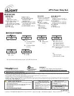
ADDITIONAL EMERGENCY (-ER) INSTRUCTIONS
PUSH-BUTTON TESTING
: As long as the relay is in the open (lights off) position and normal power is present,
you are able to simulate normal power being lost by pressing and releasing the unit’s push-button one time.
After a few seconds the relay will close for 4 seconds, then open back up and return to normal operation. A
separate push-button test switch (not included) can also be wired in as shown in above diagrams.
INTERFACING WITH A FIRE ALARM PANEL:
To interface unit to a fire alarm system such that the relay is
overriden upon activation of the fire alarm system, the fire alarm system must provide a normally closed relay
which opens when the fire alarm system is activated. This relay must be put in series with the Black power
sense line on the
nPP16 ER
. When the normally closed relay opens, the
nPP16 ER
will close its relay to
provide egress lighting when the fire alarm system is activated.
GENERAL INSTALLATION INSTRUCTIONS
BLU
(Switched Out
)
BLU
(Emer. Feed)
BLK
Normal
3
Emergency
OPTIONAL
TEST
SWITCH
WHT w/ RED
STRIPE
(Emer. Neutral)
RED
(277VAC
Emer. Feed
2
)
{
WHT
(Normal Neutral)
{
nPP16 D ER
or
nPP16 DS ER
CAT-5e
(Normal Feed)
(sense only)
YEL
120 VAC
OR
277 VAC
1
(120VAC
Emer. Feed)
GRN
(low voltage
dim out)
VIO
(low voltage
common)
GRY
EMERGENCY
0-10 VDC
Ballast or
LED Driver
Diagram for units with a dimming option
(-D or -DS suffix)
Diagram for non-dimming units
Notes
1) Connect to 120VAC or 277VAC feed ONLY. Cap off unused wire.
2) For 347V product, Red wire is 347VAC Emer. Feed
3) Normal Sense input: 120-277VAC. For 347V product: 120-347VAC


