6
Assembly
q
Insert the Brush Holder into the Frame with the chamfered
edge to the front.
Note: If it is difficult to get the lead wire terminal into the Brush
Holder, insert the terminal a little obliquely.[Fig 13]
[Fig 13]
w
With the arrow marked on the Brush Holder Retainer
pointing towards Frame, insert it obliquely as shown in Fig 14.
e
The Brush Holder Retainer can be set horizontally if you
push it in the direction of the arrow on the Brush Holder
Retainer. Slide it as far as possible in the direction of the
arrow.[Fig 14]
[Fig 14]
r
Put the lead wire in the groove in the Brush Holder Retainer
so that it does not become caught in the Motor.[Fig 15]
[Fig 15]
t
Press Switch Handle(A) into the Frame while you fit the
Core Rods and complete the assembly.
[Fig 16]
y
Tighten the Switch Handle fastening screws.
[Fig 16]
[Fig 16]
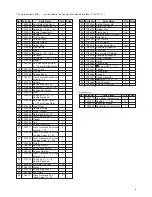
8 OPTIONAL ACCESSORIES
9 ORDERING SERVICE PARTS
In ordering parts and components, give the part number, part
name and quantity to the sales agent from whom you
purchased the tool.
Frame
Brush Holder
Chamfering Side
Slide
Core Rod
Brush Holder
Retainer
Lead Wire
Brush Holder Retainer
Switch Handle (A)
Screw
Parts No.
Parts Name
Q'ty
TP16475 Needle Supporter 2
φ
1
TA98781 Needles 2
φ×
180
100pcs.
TA98782 Needles 3
φ×
180
100pcs.


