background image

12 


MAXIMIZER-II rev A


To begin, open the log file and then click the


Analysis Plots button on the upper task bar. 


The X and Y-axis can be customized to display any 
combination of. This is done by selecting the items from 
the pull-down menus for each axis. For example, viewing 
EGO on the Y-axis and RPM on the X-axis will display 
your air-fuel ratio over your RPM range. The 

acceleration 

plot

 indicates how fast the RPM was increasing which can 

be used to compare performance from one run to the next 
as well as analyzing wheel spin or other conditions. 


You can zoom in on any section of the graph by clicking and holding the left mouse button, and then 
dragging the cursor. A box will appear which indicates the area to be zoomed. To zoom out, click on 
the Unzoom button that appears in the upper right when you zoom in. 
 
Additional features are available to customize the graph view as well as export the screen to a file or 
printer. This menu is selected by clicking the right mouse button while the cursor is over the graph. 
You can also customize your graph by double clicking on the open graph.  
 

2

2

.

.

6

6


S

S

o

o

f

f

t

t

w

w

a

a

r

r

e

e


U

U

p

p

d

d

a

a

t

t

e

e

s

s


Free updates are available for the MAXIMIZER-II and related software at 

www.fjoracing.com 

3

3

.

.


A

A

c

c

c

c

e

e

s

s

s

s

o

o

r

r

i

i

e

e

s

s


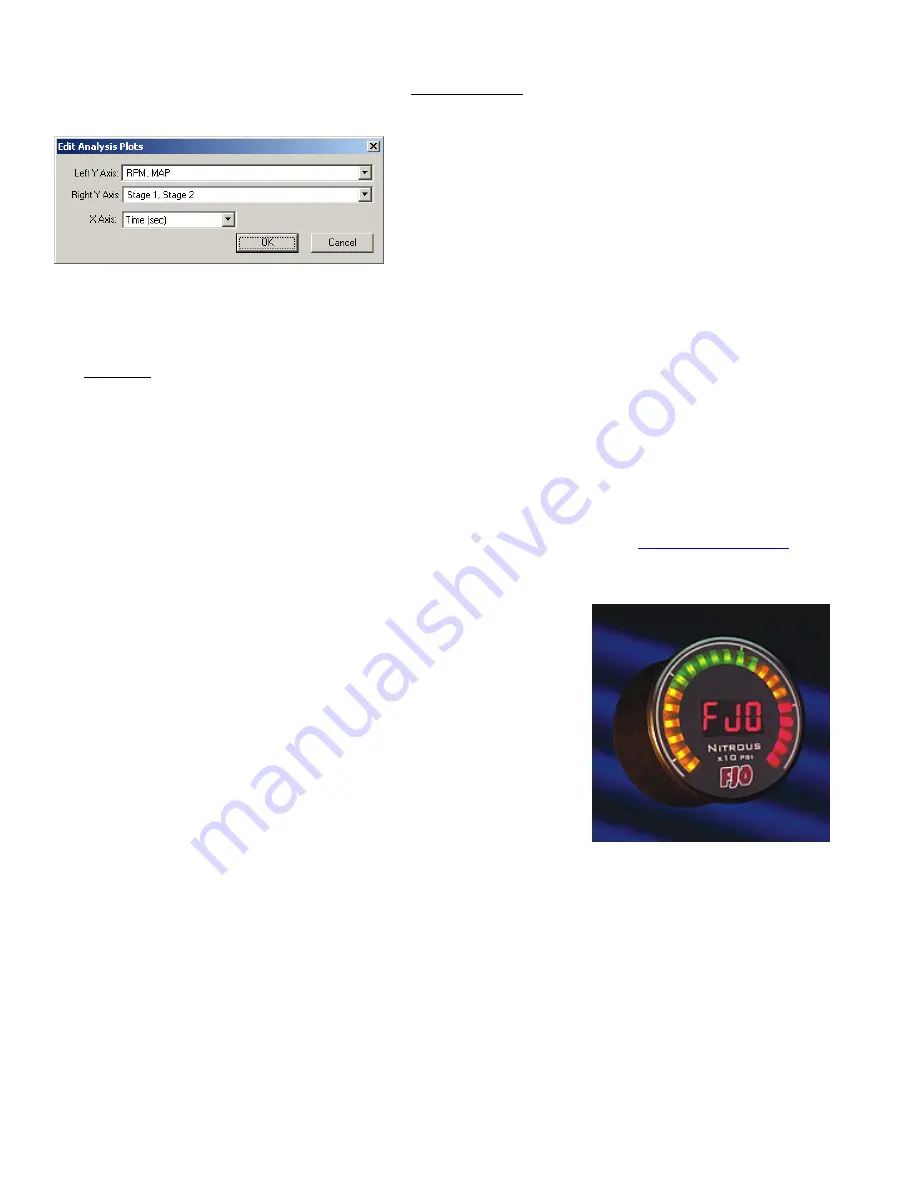
Optional accessories available for the MAXIMIZER-II include: 

• 

Nitrous Pressure Sensor 

• 

FJO Wideband Air/Fuel Ratio controller (single or 
dual channel) 

• 

AFR Gauge (digital) 

• 

Nitrous Pressure Gauge (digital) 

• 

Boost Gauge (digital) 

• 

Status Gauge (digital) 

• 

Automatic Bottle opener module 

• 

Additional Solenoid driver module 

• 

Datalogging module (available late 2005) 


Summary of Contents for MAXIMIZER-II

Page 1: ...ing Caution EXTREME DANGER Caution Do not use or mix any other manufacturer s products with any Nitrous Express products Do not use or mix any Nitrous Express products with any other manufacturer s pr...

Page 2: ...eneral Options Tab 4 2 3 2 Miscellaneous Option Tabs 4 2 4 MAXIMIZER II Configuration 5 2 4 1 General Tab 5 2 4 2 Stage 1 2 Tab 8 2 4 2 1 Time Based Nitrous Configuration 9 2 4 2 2 RPM Based Nitrous C...

Page 3: ...RIVER must be connected to a good ground location that can handle 40 AMPS DO NOT connect to the ECU ground connection While pulsing the solenoids this will generate large amounts of electrical noise t...

Page 4: ...10 0 B Bo ot tt tl le e H He ea at te er r E En na ab bl le e I In np pu ut t Grounding this input is considered the ENABLE position for the automatic bottle heater control This feature allows the MAX...

Page 5: ...t te er ri in ng g U Us se er r D Da at ta a Drag Slide data fields that have this feature have a down arrow button to the right Clicking and holding the button causes a slider bar to appear Moving th...

Page 6: ...the maximum retry count before the software displays a timeout error For most PC s this should be set to 3 Number of retries on CRC error sets the maximum retry count before the software displays a C...

Page 7: ...fjoracing com Wideband AFR System Controller is recommended It will enable the MAXIMIZER II to accurately display and log your air fuel ratio RPM Signal Present allows you to select whether or not yo...

Page 8: ...eature allows you to use the automatic bottle heater control as well as log your bottle pressure A check mark in the box tells the MAXIMIZER II that the sensor is connected and enables the automatic b...

Page 9: ...ype allows you to select the type of transmission manual or automatic If Manual there is no more configuration required for Transmission If Automatic proceed as follows Detect Gearshift Above allows y...

Page 10: ...AT and WOT is used to attenuate the nitrous ramp by as much as 35 TPS Trigger at allows you to set the throttle point above which the nitrous can be turned on EGO Cutoff allows you to set the lean poi...

Page 11: ...to the desired settings or by using the methods described in the Entering User Data section Ramp allows you to set the time taken from the START of the Nitrous to the FINAL This can be set by draggin...

Page 12: ...button green arrow pointing to car To download a configuration from the MAXIMIZER II ensure the MAXIMIZER II is turned on Open a default configuration by clicking on File then New Now click on the DOW...

Page 13: ...Open In the Files of type section select MAXIMIZER II II Logs If the log files do not appear in your window you may not be in the correct directory To change directories click on the down arrow in the...

Page 14: ...area to be zoomed To zoom out click on the Unzoom button that appears in the upper right when you zoom in Additional features are available to customize the graph view as well as export the screen to...

Page 15: ...does not warrant equipment parts or components purchased by FJO or the customer from any third party manufacturers or suppliers Rather for any defect in respect of equipment parts and components purch...

Page 16: ...14 MAXIMIZER II rev A 6 6 1 1 S Sy ys st te em m...

Page 17: ...15 MAXIMIZER II rev A 6 6 2 2 S St ta at tu us s L LE ED D 6 6 3 3 1 12 2 v vo ol lt t A Ar rm mi in ng g S Sw wi it tc ch h...

Page 18: ...16 MAXIMIZER II rev A 6 6 4 4 I Ig gn ni it ti io on n R Re et ta ar rd d 6 6 5 5 R Re em mo ot te e B Bo ot tt tl le e O Op pe en ne er r...

Page 19: ...17 MAXIMIZER II rev A 6 6 6 6 A Au ut to om ma at ti ic c P Pu ur rg ge e 6 6 7 7 F Fu ue el l P Pr re es ss su ur re e S Sa af fe et ty y C Cu ut t o of ff f S Sw wi it tc ch h...

Page 20: ...figuration to 4 5 volts the TPS TRIGGER to 95 and the IDLE to 0 5 volts Figure B illustrates how to connect a GROUND wide open throttle switch Set the WOT setting in the MAXIMIZER II configuration to...

Reviews: