NISTA DEVICES GmbH 2013
© All Rights Reserved
6
3 Installation
3.1
Physical installation
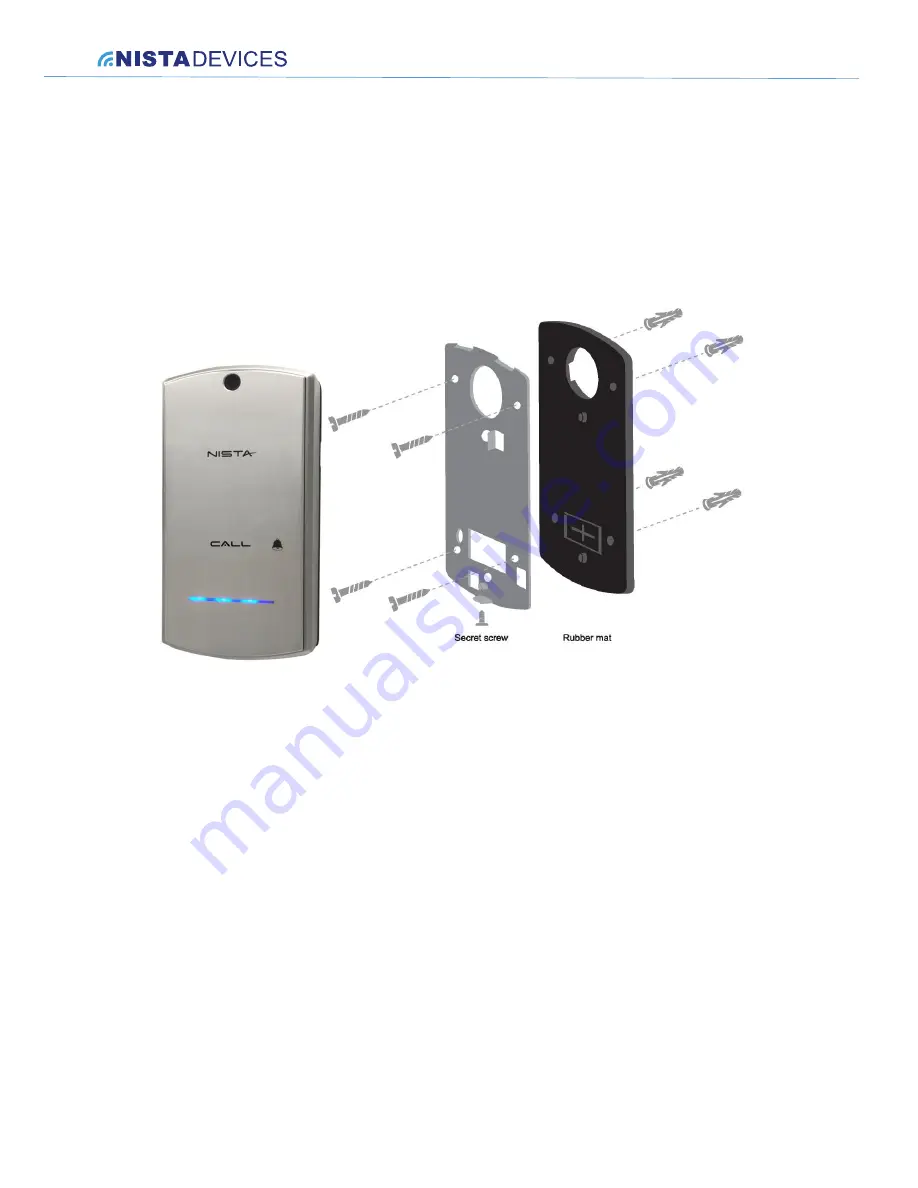
The Door phone can be mounted on the wall by using installation bracket provided with the unit.
To install the IP Door Phone Unit on the wall:
Open the IP Door Phone case by rotating the secret screw from the bottom side of the unit.
Figure 3-1 Door Phone wall installation
To install the wall bracket:
1. Measure and mark the location of the holes on the wall, where they are to be drilled.
2. Drill the holes and insert the wall dowels into the holes.
3. Place the rubber membrane on the wall and then metal unit base using the provided wall screws.( See Figure 3-1)
4. Connect all required wired connections
5. Put the
Door Phone’s front panel into the base latch mechanism, then close the case and lock with the any tamper
screw.
3.2
IP Door Phone installation
The IP Door Phone can be installed as an individual access control device.
Figure 3-2 shows the terminal locations on the wire connector provided with the unit. This connector is then inserted
into the mating connector located at the base of the internal PCB. All wiring to the unit shall be attached to the wire
connector.
The Ethernet RJ-45 socket is for the LAN network cable and PoE connection.


