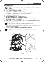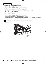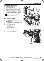
ENGLISH
USER MANUAL
24
909 6752 000(3)2010-03 A
BA 551 - BA 551D - BA 551CD - BA 611D
SQUEEGEE BLADE CHECK AND REPLACEMENT
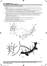
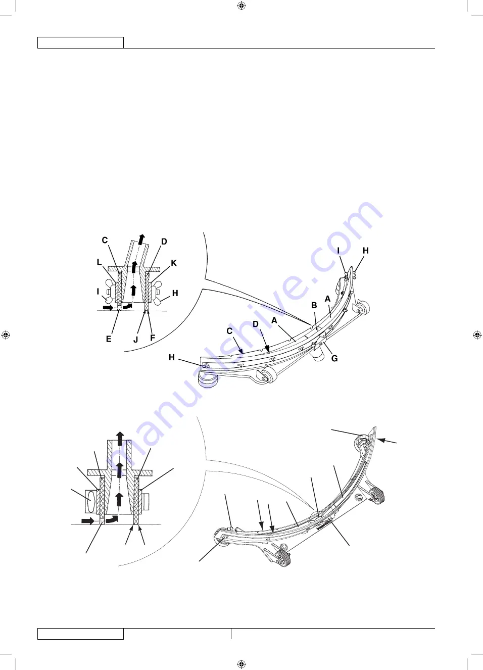
Clean the steel squeegee (Fig. 6) or the aluminium squeegee (Fig. 7), according to the procedure shown in the previous
1.
paragraph.
Check that the edges (E, Fig. 6 or 7) of the front blade (C) and the edges (F) of the rear blade (D) lay down on the same level,
2.
along their length; otherwise adjust their height according to the following procedure:
Release the tie rod (G, Fig. 6 or 7) and loosen the wing nuts (H, Fig. 6), or disengage the fasteners (M, Fig. 7) and adjust
•
the rear blade (D, Fig. 6 or 7), then tighten the wing nuts, or engage the fasteners, and then engage the tie rod.
Loosen the handwheels (I) and adjust the front blade (C, Fig. 6 or 7); then tighten the handwheels.
•
Check the front blade (C, Fig. 6 or 7) and rear blade (D) for integrity, cuts and tears; if necessary replace them according to the
3.
following procedure. Check the front corner (J) of the rear blade for wear; if necessary, overturn the blade to replace the worn
corner with an integral one. If the other corners are worn too, replace the blade according to the following procedure:
Release the tie rod (G), remove the wing nuts (H) or disengage the fasteners (M), remove the retaining strip (K), then
•
replace/overturn the rear blade (D).
Install the blade in the reverse order of removal.
Unscrew the handwheels (I) and remove the retaining strip (L), then replace the front blade (C).
•
Install the blade in the reverse order of removal.
After the blade replacement (or overturning), adjust the height as shown in the previous step.
Connect the vacuum hose (15) to the squeegee.
4.
Install the squeegee (25) and screw down the handwheels (26).
5.
If necessary, adjust the squeegee balance adjusting handwheel (27).
6.
Figure 6
S311318
I
B
A
M
G
A
D
C
I
M
K
F
J
E
D
C
L
I
Figure 7
S311318
909 6752 000(3)2010-03 A.indb 24
909 6752 000(3)2010-03 A.indb 24
04/03/2010 15.01.28
04/03/2010 15.01.28


