


Scrub System: Disc, Cylindrical, & Boost
56
Service Manual – Focus II / Scrubtec R6 Rider Autoscrubber
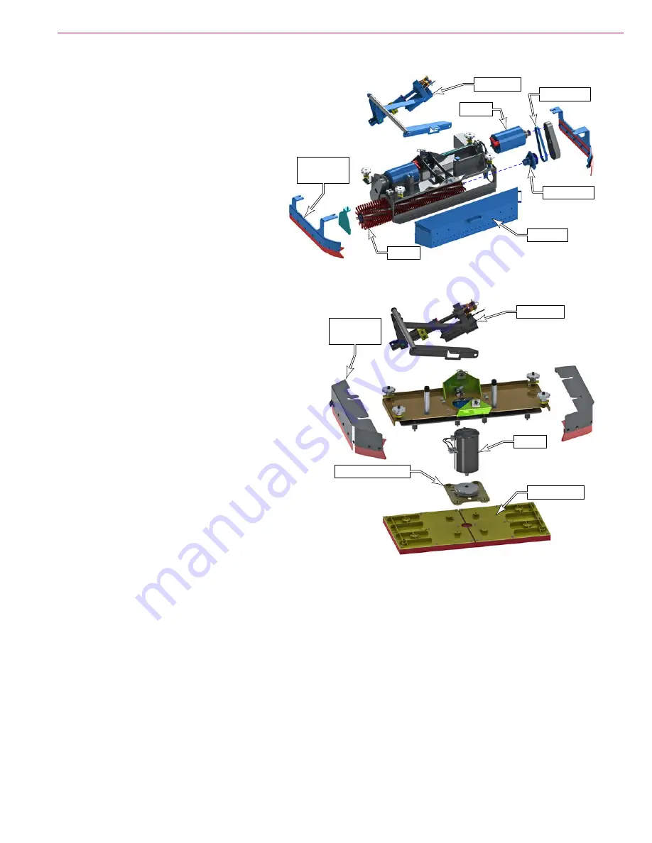
Cylindrical Deck (Nilfisk-Alto models only)
The cylindrical deck uses two counter-rotating
horizontal brushes. Each brush is driven by
its own motor via a drive pulley. The counter-
rotation is achieved because both motors
rotate the same direction, but are facing in
opposite directions from one another.
The cylindrical deck uses the same current
sensing methodology for detecting brush
pressure as the disc deck, but with slightly
different values and for only 2 motors.
The counter rotating motion of the brushes
permits large debris to be propelled into the
hopper behind the deck.
Boost Deck (Clarke models only)
The boost deck operates on an orbital motion instead
of a rotational motion. The rectangular pad moves
in a small circle but does not rotate. This orbital
movement is created from an eccentric lobe, where
the rotation of the motor’s shaft is off-axis from the
center of the pad. Rubber isolation mounts allow the
pad to move in this small circular motion without
rotating.
Because this small orbital motion results in a
significant mechanical advantage for the motor’s
rotation, current sensing for determining the deck
pressure results in only small variations in motor
current for large variations in deck pressure. For
this reason, current sensing is not used for deck
pressure control.
The lift actuator contains two extra position switches
to tell the controller what the physical position is of
the deck height. From these heights, deck pressure
is mathematically determined from the amount of
spring compression within the actuator’s leadscrew.
Circuit Overview
Scrub Deck Motors
Depending on the configuration of the machine, there will be 1, 2, or 3 brush motors. All motors are
connected in parallel from the same wiring harness. Power to the brush motor(s) is controlled by a motor
contactor, which is a motor-rated relay. When the contacts close, the circuit between the brush motor and
the positive battery power is completed. The positive terminal of the contactor coil is energized whenever the
key switch is on and the E-Stop is not engaged. The negative terminal of the contactor coil is controlled by
the Main Machine Controller.
The contactor coil is controlled by the switching of the negative terminal via the J1-13 terminal of the Focus
II control board
(A1)
. The output of the J3-13 terminal is PWM controlled to reduce the effective voltage on
the contactor’s coil. This PWM signal does not impact the actual brush motor voltage, only the coil’s voltage.
The PWM signal begins high to pull the contacts together, and then reduces power to just enough to hold the
contacts closed.
Motor
Deck Lift
Side
Squeegee
Brush
Drive Belt
Drive Hub
Hopper
Deck Lift
Side
Squeegee
Motor
Eccentric Lobe
Flex Plates


