


Recovery System
49
Service Manual – Focus II / Scrubtec R6 Rider Autoscrubber
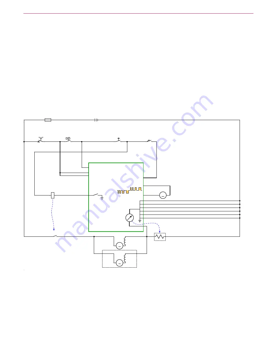
Vacuum Motor Control Circuit Overview
Power to the vacuum motor is controlled by a motor contactor, which is a motor-rated relay. When the
contacts close, the circuit between the vacuum motor and the positive battery power is completed. The
positive terminal of the contactor coil is energized whenever the key switch is on and the E-Stop is not
engaged. The negative terminal of the contactor coil is controlled by the Main Machine Controller.
The contactor coil is controlled by the switching of the negative terminal via the J3-12 terminal of the Focus
II control board
(A1)
. The output of the J3-12 terminal is PWM controlled to reduce the effective voltage
on the contactor’s coil. This PWM signal does not impact the actual vacuum motor voltage, only the coil’s
voltage. The PWM signal begins high to pull the contacts together, and then reduces power to just enough to
hold the contacts closed.
The Main Machine Controller monitors the performance of the vacuum motor by observing the voltage drop
across the negative power wire leading to the motor. The more current flowing through the wire, the larger
the voltage drop. The controller uses this voltage reading to calculate the amperage running through the
motor.
A1 MAIN MACHINE
CONTROLLER
J3-1 B+
J3-8 B+
J3-14 KEY SWITCH
SEAT
SWITCH J3-4
3
4
S1
KEY SWITCH
1
2
BT1
BATTERY, 24 VDC
+
-
CB2
CIRCUIT BREAKER
10 AMP
1
2
E-STOP
SWITCH
S4
1
2
S2
SEAT SWITCH
2
1
K1
VACUUM CONTACTOR
F1
FUSE, 150A.
1
2
Vacuum Motor
Current Sense
by Voltage Drop
OPTIONAL
M
M3
MOTOR,SQUEEGE LIFT ACTUACTOR
-
+
K1
CONTACTOR, VACUUM
1
2
M
M6
MOTOR, VAC
1
2
M
M5
MOTOR, VAC
1
2
Reversible PWM
Effective Resistance
of Ground Wire


