


08/12 Updated 08/14 Form No. 56043159
Service Manual
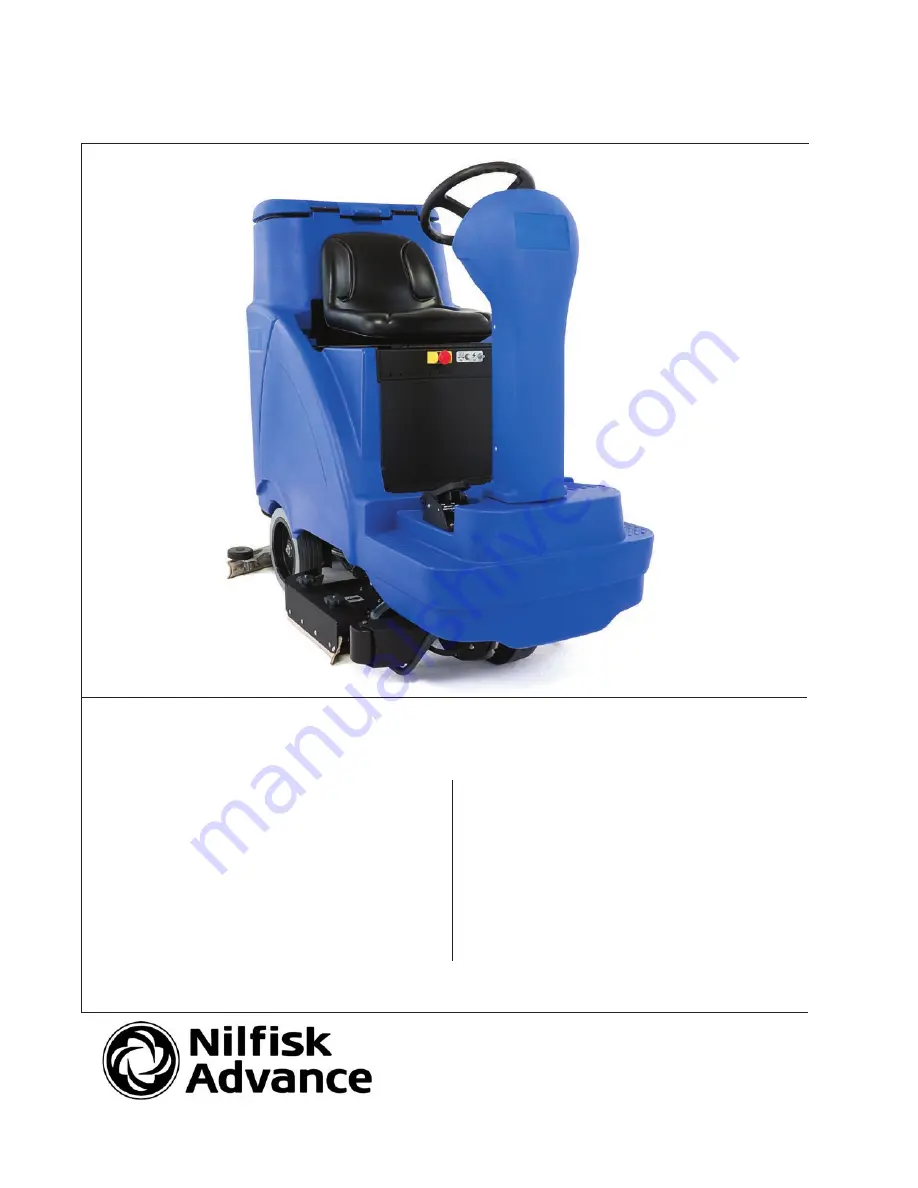
Clarke
®
model numbers:
56114000
Focus II Rider 28 D Base
56114001
Focus II Rider 34 D OBC Base
56114002
Focus II Rider 34 D Base
56114003
Focus II Rider 28 B Base
56114009
Focus II Rider 28 B OBC Base
56114010
Focus II Rider 28 D OBC Base
Nilfisk-Alto model numbers:
56114004
Scrubtec R 6-71 28D
56114005
Scrubtec R 6-71C 28C
56114006
Scrubtec R 6-86 34D
56114008
Scrubtec R 6-100 40D
English
Clarke Focus II Rider Autoscrubber
Nilfisk-Alto Scrubtec R6 Rider Autoscrubber


