background image

User's Guide for CTS6000 Control panel 


Version 1.00 

Subject to alteration without notice.  

NILAN A/S 

Page 4 of 11  

Control panel menus 

The panel consists of a "Power" button, an "Alarm" button, four arrow buttons and a "Set" button. 
The buttons have the following functions. Pressing any button for the first time activates the backlit 
display.  The  "POWER"  button  is  used  to  start/stop  the  system  in  "Weekly  program"  mode  or  to 
activate "Extended operation". The "ALARM" button is used to access the alarm log. "Arrow right" 
is  used  to  enter/open  a  menu  option.  "Arrow  left"  is  used  to  return.  "Arrow  up"  is  used  to  scroll 
upwards or to increase a parameter setting. "Arrow down" is used to scroll downwards or to reduce 
a parameter setting. The "SET" button is used to save a new setting.  
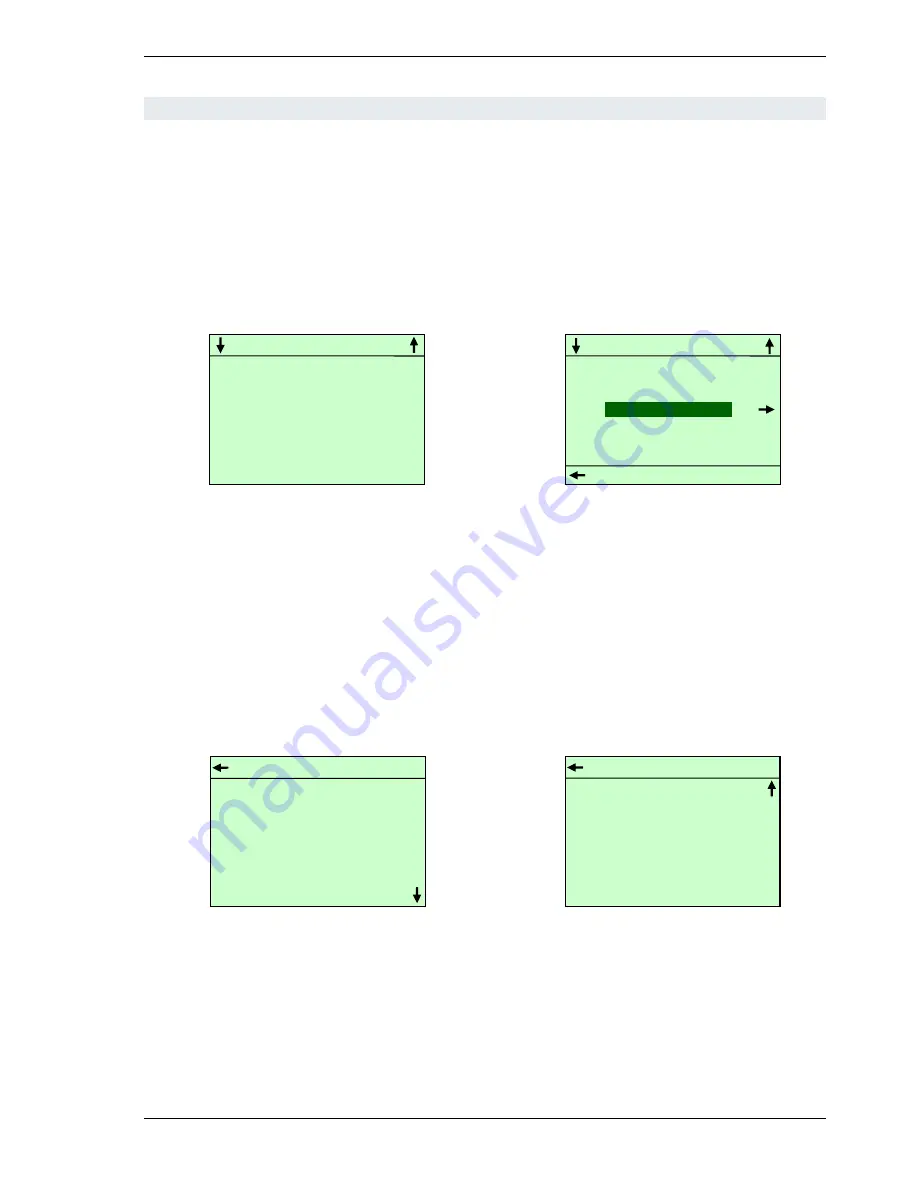
The startup display shows current system status, see Figure 1. The main menu is opened from the 
startup display using the arrow up or arrow down button, see Figure 2. 


Figure 1 Panel startup display


Figure 2 Menue


The startup display reappears if no button is pressed for 15 seconds. 


Alarm log/event log 

The alarm log is accessed by pressing the "ALARM" button, i.e. the one marked with a bell on the 
bottom right of the panel. The most recent alarms/events will then be displayed, see Figure 3. It is 
possible to scroll through previous alarms/events using the arrow up and down buttons.  


Figure 3 Alarm log with new alarm 

Figure 4 Alarm log with no alarm 

 
In  the  event  of  a  new  alarm,  the  red  lamp  above  the  alarm  button  will  flash.  Press  the  button  to 
view  the  alarm  and  then  press  "SET"  to  reset  the  alarm,  see  Figure  4.  If  the  system  has  been 
stopped as a result of an alarm, it will be restarted once the alarm has been reset in the alarm log if 
the error that caused the alarm has been remedied. 


GO TO MENU 

CONTROLLING SENSOR : 

20.3 C 

SETPOINT : 


20.0 C


WEEKLY 

PROGRAM 


MENU 

EXIT 

LANGUAGE SELECTION 


WEEKLY PROGRAM 


SYSTEM INFORMATION 


MENU 

LANGUAGE SELECTION 


WEEKLY PROGRAM 


SYSTEM INFORMATION 


EXIT 


ALARM LOG 

13-03-2009   

12:55 

System started 
 
13-03-2009   

12:52 

System stopped 


ALARM LOG 

No new alarms 

All manuals and user guides at all-guides.com

Summary of Contents for CTS6000

Page 1: ...User s Guide CTS6000 control panel Version 1 03 2014 06 25 Valid for SW version 1 0088 All manuals and user guides at all guides com a l l g u i d e s c o m ...

Page 2: ...oint menu 6 Menu overview 9 Description of alarms 10 Figure Figure 1 Panel startup display 4 Figure 2 Menue 4 Figure 3 Alarm log with new alarm 4 Figure 4 Alarm log with no alarm 4 Figure 5 Power System in Operation 5 Figure 6 Weekly program 5 Figure 7 Selecting the manual set point mode 6 Figure 8 Manual mode parameters setting 7 Figure 9 Manual mode parameters setting 7 Figure 10 Java GUI manual...

Page 3: ... operation to be viewed and altered It is thus possible to change various temperature settings reset alarms and start the unit outside the usual operating period The CTS6000 control panel supplements CTS6000 WebControl the program in which more advanced settings are made A menu overview and descriptions of all alarms can be found at the end of the guide All manuals and user guides at all guides co...

Page 4: ...tup display Figure 2 Menue The startup display reappears if no button is pressed for 15 seconds Alarm log event log The alarm log is accessed by pressing the ALARM button i e the one marked with a bell on the bottom right of the panel The most recent alarms events will then be displayed see Figure 3 It is possible to scroll through previous alarms events using the arrow up and down buttons Figure ...

Page 5: ...hen press arrow right to open the weekly program see Figure 6 Use arrow up or arrow down to scroll through the various menu options for the day selected As standard Monday is initially displayed when the weekly program is opened Six program events can be defined for each day of the week Figures at the top of the display indicate the number of events defined for the day in question For each program...

Page 6: ...access the service menu activate the control panel by pressing arrow down Then press and hold SET for approx 10 seconds The service menu will then appear Manuel Set point menu To enter the manual set point mode one should hold power button until the corresponding menu appears see Figure 7 Selecting the manual set point mode After selecting the mode one is able to adjust manual mode parameters see ...

Page 7: ...ter 2 Parameters editing a Button SET start of value editing b Buttons Up Down change a value 1 1 c Button Left cancel editing d Button SET store a changed value 3 Return back from menu sub menu Button Left After the new week program begins the system automatically switches to auto mode turning the manual mode off Figure 8 Manual mode parameters setting Figure 9 Manual mode parameters setting All ...

Page 8: ...User s Guide for CTS6000 Control panel Version 1 00 Subject to alteration without notice NILAN A S Page 8 of 11 Figure 10 Java GUI manual mode in PI Diagram All manuals and user guides at all guides com ...

Page 9: ... 23 7 C ANALOG1 100 ANALOG2 100 ANALOG3 000 ANALOG4 000 ANALOG5 000 ANALOG6 100 MONDAY PROGRAMME 1 2 PROGRAM POINT AKTIVE TIME 17 00 VENTILATION NORMALE SET POINT 20 0 COPY TO NEXT NO Week programme Date Time Language Unit Information Min Sommer Regulation Change Present Language Change Network IP Min Winter Netmask Max Sommer Winter Week Programme Restart Unit LA SORTIE SET CHANGE Date Time Statu...

Page 10: ...hour however Condenser high pressure ID 8 11 Level 4 Upper limit 2 for cooling circuit pressure set under Pressure limits has been exceeded The alarm can be activated by insufficient air flow through the unit This may be caused by blocked filters loose V belts or dampers which have not opened Reset alarm If the alarm repeatedly occurs for no apparent reason call service Evaporator low pressure 1 I...

Page 11: ...utes and reset the alarm Pressure pipe temperature T10 11 12 13 ID 50 51 52 53 Level 2 Pressure pipe temperature on compressor 1 2 3 4 has exceeded 125 C The controls stop the compressor and do not allow it to restart before the temperature has dropped below 50 C If the alarm repeatedly occurs call service VLT x has not responded to the 5 latest requests ID 111 Level 4 A communication error has oc...

Reviews: