background image

14

5

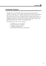
Insert the eyepieces into the eyepiece sleeves.

Be sure that it is inserted all the way to the end of the sleeve.

Note) When inserting the 10X eyepiece, assure that it reaches the end of

the sleeve, because the rubber cover of the 10X eyepiece will
obstruct the view of the sleeve end.  When inserting, hold the rubber
cover instead of the diopter ring.  If not, it may result in the damage
to the product.

6

Attach the camera head (optional).

Remove the C mount cap from the zooming
body.
Mount the C mount adapter to DS camera
head first. Then, attach the DS camera head to
the C mount of the zooming body.
The direction of DS camera head can be
adjusted by loosening the fixing screw and
rotating the C mount.

7

Adjust the torque of the focus knob.

Adjust the torque of the focus knob so as not
to fall down the zooming body by its own
weight.

8

Storing the tools

The hexagonal wrenches can be stored at the rear of the focusing stand.
Refer to the figure on p.9.

Increase the torque

(To reduce the torque,
turn the knob in the direction
opposite to the arrow.)

Summary of Contents for SMZ745T

Page 1: ...Stereoscopic Zoom Microscope SMZ745T Instructions M518E 09 7 NF 1 ...

Page 2: ......

Page 3: ...change without notice Although every effort has been made to ensure the accuracy of this manual errors or inconsistencies may remain If you note any points that are unclear or incorrect please contact your nearest Nikon representative Some of the equipment described in this manual may not be included in the set you have purchased If you intend to use any other equipment with this product read the ...

Page 4: ...uct Do not discard this manual and keep it handy for easy reference Safety instructions in this manual are marked with the following symbols to highlight their importance For your safety always follow the instructions marked with these symbols Symbol Description Disregarding instructions marked with this symbol may lead to serious injury or death Disregarding instructions marked with this symbol m...

Page 5: ...t the input voltage displayed on the power supply of the illuminator matches the operating voltage Please contact your nearest Nikon representative if the displayed voltage does not match the operating voltage Use of an improperly matched illuminator may result in damage to the equipment 5 Cautions on the power cord The power supply is necessary for using the halogen illuminators which are accesso...

Page 6: ...tions on lamp replacement When replacing the lamp wait approximately thirty minutes after turning off the lamp and make sure that the lamp and the lamphouse have cooled sufficiently To prevent electric shock and product damage turn off the power switch on the power supply before replacing the lamp 1 Check the light source When using an illuminator be sure to use the specified rating only Use of ot...

Page 7: ... in a location subject to direct sunlight Install the product in a location with little vibration Install the product in a location with little dust and dirt 3 Cleaning the lenses Do not allow dust fingerprints or any other dirt to get on the lenses Dirt on the lenses will degrade the image quality If a lense becomes dirty clean them as described below Use an air blower to blow dust away Remove an...

Page 8: ...y result in deformation of the part or removal of lettering 5 Storage Store the product in a dry location where mold is unlikely to grow Do not store the product in a location subject to direct sunlight or high temperature and humidity Put a dust proof cover over the product to protect it from dust 6 Regular inspections Paid service Regular inspections are recommended in order to maintain the peak...

Page 9: ...upillary distance 10 4 Adjust the diopter 11 5 Change the zooming magnification 11 6 Change the optical path 12 7 Image cannot be focused even with the zooming body at the highest position 12 III Assembly 13 Antistatic Feature 15 IV Using Accessories 16 1 Reticles 16 2 Halogen Illuminators 17 Table 1 Total Magnification and Real Field of Binocular Tube 23 Table 2 Total Magnification and Real Field...

Page 10: ...C mount Nikon DS camera head can be attached Changes the light distribution between the vertical tube and the right eyepiece tube Refer to 6 Change the optical path on p 12 Optical path switching lever C mount cap Eyepiece 10X 15X 20X and 30X eyepieces are available Diopter ring Refer to 4 Adjust the diopter on p 11 Zooming body Outside diameter of the part to be mounted on the arm ø76 Zooming bod...

Page 11: ...r Holds the G LS 6V10W halogen illuminator Zooming knob clicks ON OFF screw inside Refer to ON OFF of the zooming knob clicks on p 11 Hexagonal wrench hanger Stores the supplied hexagonal wrenches Hexagonal wrench Large Pillar Supplied with the focusing stand for changing the height of the arm Ground jack Refer to Antistatic Feature on p 15 Hexagonal wrench Small Supplied with the zooming body for...

Page 12: ...s bottom surface is 115 mm apart from the sample surface Refer to Table 1 p 23 for changing the working distance when the auxiliary objectives are attached The torque of the focus knob If the torque of the focus knob is too light the zooming body falls down by its own weight Adjust the torque to an appropriate weight Refer to 7 Adjust the torque of the focus knob on p 14 3 Adjust the interpupillar...

Page 13: ...he sharp image throughout the zooming range This adjustment should be performed each time the observer is changed since individual eyesights vary 5 Change the zooming magnification The magnification of the sample image will change by turning the left and right zooming knobs of the zooming body Choose the desired magnification Total magnification The right zooming knob from the viewing side has the...

Page 14: ...e instruction of the camera head for the details of the Nikon DS Camera Head operation Refer to Table 2 p 24 for Total Magnification and Real Field of Vertical Tube 7 Image cannot be focused even with the zooming body at the highest position For using the 0 5X auxiliary objective or for observing a tall sample you may not be able to focus on the sample even if turning the focus knob to raise the z...

Page 15: ...th the focusing stand to loosen the arm fixing screw Reattach the arm using the screw hole at the lower side of the vertical slider The arm will become 55 mm lower than its original position Before tightening the screw make sure that the two pins on the arm are inserted into the grooves in the vertical slider 4 Mount the zooming body Lightly tighten the zooming body clamp screw to hold the zooming...

Page 16: ...head optional Remove the C mount cap from the zooming body Mount the C mount adapter to DS camera head first Then attach the DS camera head to the C mount of the zooming body The direction of DS camera head can be adjusted by loosening the fixing screw and rotating the C mount 7 Adjust the torque of the focus knob Adjust the torque of the focus knob so as not to fall down the zooming body by its o...

Page 17: ...microscope on this purpose change the stage plate to antistatic ESD stage plate and ground the microscope through the ground jack at the rear of the plain focusing stand The φ 4 mm grounding terminal can be inserted into the ground jack The following accessories are also antistatic C FPS Fluorescence Attachment Auxiliary Objectives all types C FMB Focusing Mount B G US1 and G US2 Universal Table S...

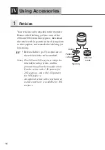
Page 18: ...h the field ring or lens room Refer to Table 1 p 23 for the size of the reticle which can be attached Note The 20X and 30X eyepieces adopt the internal focusing system and the primary image has the magnification Use the reticle with 1 3X pattern for 20X eyepiece and with 1 4X pattern for 30X eyepiece An optional reticle with cross hairs or scaled cross hairs is available for 10X eyepiece Optional ...

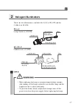
Page 19: ...ap ø33 mm filter attachable Holder and Epi arm mounting screw hole IV G LS Lamp Socket A 6V10W C DSLS Illuminator A 6V20W 1 Lamp When replacing the lamp wait approximately thirty minutes after turning off the lamp and make sure that the lamp and the lamphouse have cooled sufficiently To prevent electric shock and product damage turn off the power switch on the power supply before replacing the lam...

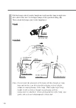
Page 20: ... it may burn and stick to your skin possibly reducing its level of light output or causing damage to the lamp When replacing a lamp handle it with a cloth or through its packaging until the replacement is completed If you get fingerprints on the lamp wipe gently with a clean cloth dampened with alcohol Socket Lamp GE 787 6V 10W Socket Small protrusion Holder mounting screw hole Light shielding tub...

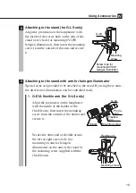
Page 21: ...ion of illumination can be controlled easily 1 G EIA flexible arm for G LS only Align the protrusion on the lamphouse with the inside of the holder of the flexible arm then insert the mounting screw from the outside of the holder and secure it Secure the other end of flexible arm to the left or right screw hole for mounting an arm for halogen illuminator on the arm of the stand by the mounting scr...

Page 22: ...on the lamphouse as described above Set the lamphouse in a position for easy viewing and tighten the clamp knob 4 Lighting area adjustment for G LS only You can adjust the lighting area by moving the lamp socket back and forth Adjust the lighting area to allow easy viewing 5 Attaching filters for C DSLS only Rotate and remove the filter cap at the end of the lamphouse and insert a filter Use filte...

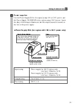
Page 23: ...age display Check that the voltage displayed matches the voltage used in your area If the voltages do not match do not use the power supply and contact your nearest Nikon representative Fuse Always use the specified fuse 250 V 1 A Rear view Power cord Output connector Connect the lamphouse cable here Power switch Brightness adjuster Changes the illumination brightness when rotated Input rating Pow...

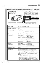
Page 24: ...ger or fire The protection Class I equipment should be connected to PE protective earth terminal For 220 to 240 VAC area Approved according to EU EN standards 3 conductor grounding Type H05VV F 3 m long maximum rated at 250 VAC minimum Power Supply TN PSE30W A for regions with 230 V power only Rear view Connect the lamphouse cable here Power cord Output connector AC input connector Brightness adju...

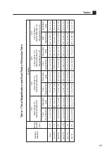
Page 25: ...one 115 6 7 to 50 X 32 8 to 4 4 10 to 75 X 23 9 to 3 2 13 4 to 100 X 18 7 to 2 5 20 1 to 150 X 10 4 to 1 4 AL0 29 X 311 1 9 to 14 5 X 113 2 to 15 2 3 to 21 8 X 82 3 to 11 0 3 886 to 29 X 64 3 to 8 6 5 8 to 43 5 X 36 0 to 4 8 AL0 5 X 211 3 4 to 25 X 65 7 to 8 8 5 to 37 5 X 47 8 to 6 4 6 7 to 50 X 37 3 to 5 0 10 1 to 75 X 20 9 to 2 8 AL0 7 X 150 4 7 to 35 X 46 9 to 6 3 7 to 52 5 X 34 1 to 4 6 9 38 t...

Page 26: ...1 0 to 36 42 to 147 AL0 29 X AL0 5 X 0 to 36 AL0 7 X 0 to 42 0 to 98 AL1 5 X 25 to 129 0 to 74 81 to 185 AL2 X 43 to 147 0 to 92 99 to 203 None 115 0 37 to 2 75 29 9 to 4 0 AL0 29 X 311 0 11 to 0 80 102 9 to 13 8 AL0 5 X 211 0 18 to 1 38 59 7 to 8 0 AL0 7 X 150 0 26 to 1 93 42 6 to 5 7 AL1 5 X 61 0 55 to 4 13 19 9 to 2 7 AL2 X 43 5 0 74 to 5 50 14 9 to 2 0 Working distance mm Vertical tube 0 55 X ...

Reviews: