background image

Digital Microsopy Center, University of Washington


July 29, 2016   


6


6.


Controlling epi-fluorescence 

6.1.


Select filters for specific wavelength bands (“colors”) by the black slider located on the 
front of the microscope betwee the eyepieces and objective lens turret; 

6.2.


There is only room for 3 filters cubes 

6.2.1.


A 4

th

 cube requires manually removing filters, usually the Cy5 and DAPI cubes 

are swapped, see DMC staff for instruction on changing the 4

th

 filter 

6.3.


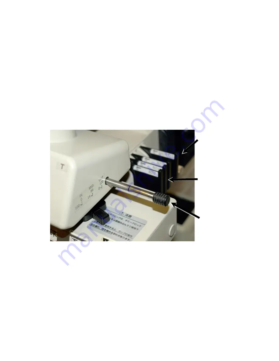
Xenon lamp intensity is controlled by pushing ND filters in or out of the light path 

6.3.1.


located behind the trinocular head (Figure 3); 

6.4.


Xenon excitation is controlled by a slider located between the ND filter and the xenon 
lamphousing (Figure 3) 

6.5.


The excitation light is also blocked when the filter slider is in the “DIA” position for 
transmitted light (diascopic illumination)  


Fluorescence 
Shutter 


ND Filters 


Trinocular 
beamsplitter 

Figure 3. Trinocular Head and Fluorescence ND Filters


Summary of Contents for Optiphot

Page 1: ...the trinocular beamsplitter to direct the image to the eyepieces 2 Brightfield 2 1 Turn on the microscope lamp 2 1 1 black push button at left front base of microscope 2 2 Select your objective lens 2 3 Set the trinocular beamsplitter to direct the image to the eyepieces 2 4 Select DIA on filter slider 2 5 Adjust lamp intensity with slider across base of microscope 2 6 Focus on the specimen 2 7 Se...

Page 2: ...7 If the bulb fails to ignite it may be too hot from prior use the bulb may be faulty or may need to be reseated Contact facility staff 2 Transmitted Illumination with halogen lamp Figure 1 2 1 Power switch turned on by the black switch left front corner of the microscope base 2 1 1 This lamp is used for brightfield phase contrast and darkfield microscopy 2 2 Lamp intensity is controlled by 3 mean...

Page 3: ... Filter Light Reduction Transmission ND2 1 2 50 ND4 1 4 25 ND16 1 16 6 25 ND2 ND4 1 8 12 5 ND2 ND16 1 32 3 125 ND4 ND16 1 64 1 562 ND2 ND4 ND16 1 128 0 781 Condenser focus Substage field diaphragm Brightfield lamp power Brightfield lamp voltage Figure 1 Sub stage Controls Fine Focus Coarse Focus Transmitted Light ND Filters Photo switch ...

Page 4: ...and weak fluorescence but large working distance 4 1 2 low magnification providse large field of view but may not magnify sufficiently for full resolution at the camera Locking screw for stage rotation Condenser diaphragm NA adjustment Centering screws for condenser alignment Lever to flip condenser top lens in or out of optical path Stage Y axis motion Stage X axis motion Figure 2 Sub stage Conde...

Page 5: ...ximum brightness 3 4 Make certain the condenser top lens is flipped up 3 5 Close the field stop diaphragm to its minimum diameter 3 6 Use the condensor focus knob to bring the leaves of the field stop sharply into focus while observing through the eyepieces 3 7 Roughly center the spot of light with the centering screws 3 8 Open the field stop until it just reaches the edge of the field of view 3 9...

Page 6: ...d DAPI cubes are swapped see DMC staff for instruction on changing the 4th filter 6 3 Xenon lamp intensity is controlled by pushing ND filters in or out of the light path 6 3 1 located behind the trinocular head Figure 3 6 4 Xenon excitation is controlled by a slider located between the ND filter and the xenon lamphousing Figure 3 6 5 The excitation light is also blocked when the filter slider is ...

Page 7: ...signated as 160 do not require a coverslip Lenses designated as 160 17 require a coverslip of 170 µm thickness Filter Label Cube Label Color Part Nikon FITC HQ FITC green 96170 C01174 TxR HQ TXRD red 96172 C00178 UV UV 2E C blue blue Cy5 Cy5 far red 31023 C81736 Lens µm pixel pixel µ m 1 mm reticle field 1 04 Plan 160 8 40 0 12 2 05 Plan 160 4 24 0 24 4 1 EPlan 160 2 12 0 47 10 40 EPlan 160 0 87 1...

Reviews: