EN
40
10-35x
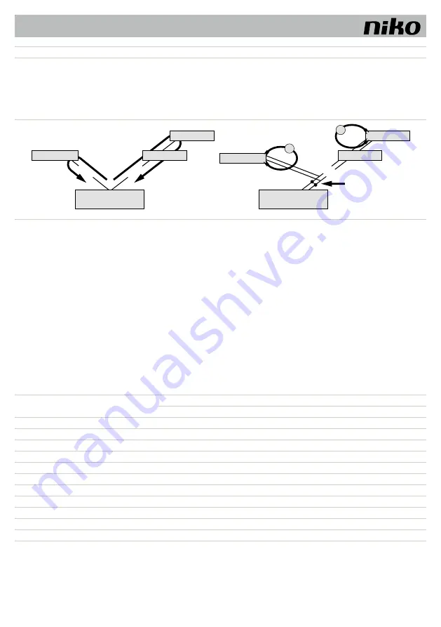
Principle of line resistance
Measuring line resistance
No external unit, internal unit or function extension shall have a longer
distance from the power supply & control units than 20 Ω.
Perform measurement:
Switch off 230 V / 50 Hz of the power supply & control unit.
Connect a/b short circuit to the power supply & control unit.
All other devices do not disturb the measuring process and can remain
connected.
Measure the a/b resistance of the last internal or external unit on the line.
Short circuit a/b here
a/M
Internal unit
Internal unit
Internal unit
Internal unit
b/P
Power supply
& control unit
Power supply
& control unit
External unit
External unit
Ohm
Ohm
maximum 20 Ohm
maximum 20 Ohm
a/b
, P/M
a/b
, P/M
20 Ω rule:
Distance from bus power supply to the farthest external or internal unit:
•
max 160 m at a diameter of 0.6 mm,
•
max 280 m at a diameter of 0.8 mm
11.3. Video kits
11.3.1.
6-wire operation
• The 6-wire operation is standard. Video mode, in which two separated earth cables (b and M) are used.
• The course of the cables depends on the buildings conditions. It depends on the length of the cables.
• When choosing the length of the cables, keep in mind the maximum line resistance of 8 Ω (a-b and M-P).
• If line resistance is > 8 Ω, extra cables must be foreseen for the lines (double twisted cables).
• You can opt for either star-shaped or linear wiring.
• Do not place more than 20 internal video units on one line. In case of more internal video units, also provide video splitters.
• On one installation up to 64 external units (including 16 external video units) and an almost unlimited number of internal units without polarity (a/b) can be
connected (only applies for 6-wire operation). Note: a suitable power supply & control device must be used.
11.3.2.
Table: line resistances video kits
Wire length a-b / M-P
in m
Diameter of wires
0,6 mm
0,8 mm
Line resistance in Ω
10
1,28
0,71
20
2,55
1,43
30
3,83
2,14
40
5,10
2,86
50
6,38
3,57
60
7,65
4,29
70
5,00
80
5,71
90
6,43
100
7,14


