NIFTYLIFT SD34T Series Operating/Safety Instructions Manual Download Page 34

 SD Series 

Operating & Safety Instructions


USA  10/12


32 


4.7 

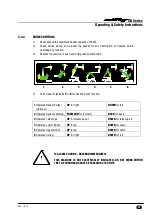
TRANSPORTING, TOWING, CRANEAGE, STORAGE AND SETTING TO WORK 


4.7.1 

TRANSPORTING 

If a Niftylift  is to be moved over a longer distance, whether the machine is trailer mounted, vehicle 
mounted, self propelled or tracked, the following procedure should be read before restraints are 
attached to the machine.  Cross loading is most frequently the cause of problems, as the method of 
loading is no longer in sight of our own personnel.  The recommendations made herein should be 
passed on to subsequent carriers, such that the entire journey is carried out without incident.


Always ensure the truck or trailer you are loading or towing the Niftylift with can carry it legally. 


If loading by crane the use of shackles and an adequately rated spreader beam, with four leg slings, 
is 

MANDATORY.


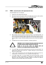
When loading or un-loading from the side of the vehicle, the use of the forklift pockets to retain one 
of the forks is recommended.  (If fitted).  Spread the forks to their widest capacity, with due regard 
to the components fitted to the machine.  Never forklift or crane an entire machine under  the 
booms, always lift beneath the spine or under the ends of the axle mountings in the case of a self-
propelled unit. Ensure forklift is adequately rated for the load to be carried. 


Once positioned on the transport carrier ratchet straps should be used to secure the machine. The 
machine should be positioned to allow easy access around the machine in transit, and to ensure 
that ‘creepage’ during transport does not permit the machine to come into contact with other goods 
being shipped, or the container itself.  Some movement of the machine structure might occur during 
transit, which could lead to fretting or other damage. 


If the machine is equipped with a transit device such as a boom clamp etc, this should be securely 
applied. 


Strap booms carefully to constrain them from sideways movement. When using straps or chains, 

adequate packing should be applied to stop any damage to the structure and paintwork.  Due regard 
of the movement of the straps or chains must be taken into account. 


Where a machine has designated points for strapping, lifting or forking, these can be used for tie-
down duty.  When they are absent, the major structure of the basket  can be used, giving due 
consideration to the design and function of the area chosen.  Where possible, use the spine of the 
machine or axle mounts over which to apply the holding down forces.  Using a single plate, such as 
an outrigger or stabiliser support plate might be unsuitable.  If the component was clearly not 
designed to accommodate a side load, one should not be applied.


Under no circumstances should straps or chains be applied over booms or through the basket 

support structure or the basket itself.  The relative strength of the carrying structure is not conducive 
to the massive forces capable of being applied through ratchet chains or slings.  Severe damage to 
the steelwork can be caused, as well as deformation to sensitive mechanisms such as basket 
weigh assemblies, which would render them useless.  Such catastrophic damage to say, an 
electronic load cell would require the component to be replaced before the machine would function. 

Summary of Contents for SD34T Series

Page 1: ...t c o m com SD34T Operating Safety Instructions MODEL SD34T SERIES M50413 02 SD34T Niftylift Limited 1525 S Buncombe Road Greer SC 29651 USA www niftylift com e mail niftyusa niftylift com Tel 864 96...

Page 2: ......

Page 3: ...perational Safety Check Schedules 13 15 3 4 Placard Decals and Installation 16 17 3 5 Torque Requirements 18 4 OPERATION 4 1 Control Circuit Components 19 21 4 2 Setting up Procedures 22 4 3 Ground Co...

Page 4: ...rbidden One of the most important facts to remember is that any equipment is only as safe as those who operate it DANGER WARNING CAUTION IMPORTANT INSTRUCTIONS AND NOTICE Any place these topics may ap...

Page 5: ...ft SD Self Drive is a range of extremely versatile articulating boom mounted via a 360 powered swing mechanism Driven from the basket the Niftylift SD34T Self Drive accommodates up to two men and thei...

Page 6: ...H STOWED 12ft 10in MAXIMUM CAPACITY 500lb TURRET ROTATION 406 TURRET TAILSWING Zero BASKET SIZE LENGTH x WIDTH 25in x 44in CONTROLS Full proportional hydraulic HYDRAULIC PRESSURE 2900psi GRADEABILITY...

Page 7: ...te is attached to Boom 1 on each machine at the time of manufacture on every Niftylift Please ensure all sections have been stamped and are legible Electrical and hydraulic circuits See drawings liste...

Page 8: ...SD Series Operating Safety Instructions USA 10 12 6 1 6 EC DECLARATION OF CONFORMITY Typical...

Page 9: ...all be given a visual inspection and functional test including but not limited to operating and emergency controls safety devices personal protective clothing including fall protection air hydraulic a...

Page 10: ...e functions for booms and telescope to position the basket for safe entry THE BASKET FLOOR MUST BE WITHIN 400MM 16IN OF THE GROUND WHEN ENTERING OR EXITING DO NOT CLIMB IN OR OUT OF THE BASKET WITH TH...

Page 11: ...operation from his management or owner dealer or manufacturer before further operation of the Niftylift 2 1 27 The operator shall immediately report to his superior any problems or malfunctions of th...

Page 12: ...to exceed 23 to 93 Celsius Extended operation in dusty environments is not recommended frequent cleaning will be necessary All dust dirt salt encrustation excess oil or grease should be removed Deposi...

Page 13: ...is then subjected to static overload tests on flat level ground with 150 of the SWL exceeding the requirements of EN280 for power operated MEWPs Self propelled machines are also tested at the maximum...

Page 14: ...perating instructions Carry out the Inspection service pre hire check list see pages 38 39 before placing machine in service 3 2 PREPARATION FOR USE Whilst every effort has been made at the Niftylift...

Page 15: ...and emergency stop buttons function properly 9 Check the operation of the manual hand pump 10 Check that warning lights beacons and sounders function correctly 11 Visually inspect all hydraulic hoses...

Page 16: ...knuckle pin is secure and the roll pin is in place 13 Lightly oil the outrigger pad ball joints outrigger housings and locating pins 14 Check that the bolts holding the wheel motors to the chassis are...

Page 17: ...f a professional engineer and must a consider the service history of the aerial platform in terms of hours of service severity and number and variability of users b review the inspection and maintenan...

Page 18: ...direction P14784 1 16 Harness Point P14883 2 17 Basket Gate Warning P18432 1 18 Operating Instructions P14892 1 19 Point Load 14 5 kN P24697 4 20 Footswitch P14884 1 21 Head Protection P14921 1 22 Rem...

Page 19: ...SD Series Operating Safety Instructions USA 10 12 17...

Page 20: ...REMENTS SCREW QUALITY SIZE Tightening torque in ft lbs Nm Grade 8 8 10 9 M 6 7 4 10 10 14 M 8 18 5 25 26 35 M 10 36 49 51 69 M 12 65 86 89 120 M 14 100 135 140 190 M 16 155 210 218 295 M 18 215 290 30...

Page 21: ...inked into the battery management system such that when low battery state is reached the pulsing of the DC motors is mimicked by the Klaxon re enforcing the message to the operator to re charge the ba...

Page 22: ...E Generally a Kubota D722 E engine described in the maintenance section of the Workshop Manual driving a twin bodied pump with direct mounted pump dump valves one per section The arrangement allows tw...

Page 23: ...ally routes the hydraulic flow through to the outrigger and drive circuit and at the same time operates the micro switch to run the appropriate power option chosen This then permits the use of either...

Page 24: ...outrigger drive position For four wheel drive machine grasp and hold duty selector Power will be available automatically 9 From the basket control station depress and hold the green power button or f...

Page 25: ...the SD34T will automatically default to the primary power source usually battery GASOLINE ENGINE OR GASOLINE ELECTRIC MODELS 8 For a cold engine start go to step 9 or for a warm engine go to step 10...

Page 26: ...o follow this procedure could result in serious injury or risk of death 4 3 2 BOOM FUNCTIONS A Push and hold green power button 1 2 3 4 B Select lever 1 2 3 or 4 for desired boom function 1 Operates T...

Page 27: ...the Start position fully clockwise and the engine will fire 7 WARM ENGINE turn the main engine ignition switch on the basket control box to the Start position clockwise and the engine will fire GASOL...

Page 28: ...ON BI ENERGY MODEL SHOWN 4 4 3 DRIVE AND OUTRIGGER FUNCTIONS Situated at the top of Boom 1 superstructure is the 4 lever drive outrigger hand valve These control the following functions Control the ja...

Page 29: ...ver 1 2 3 4 5 or 6 for desired boom function 1 Operates Basket Swivel optional UP for right DOWN for left 2 Operates Basket Levelling FORWARD for forward BACK for back 3 Operates Telescope UP for tele...

Page 30: ...ne speed control will proportionally increase the pump displacements as required Use low revs for low speed and accurate positioning 4 Select drive joystick from hand lever controls Right hand lever s...

Page 31: ...eries are charging and between 0 50 capacity Constant Green 50 LED and pulsing Green 75 LED Batteries are charging and between 50 75 capacity Constant Green 50 75 LED s plus pulsing Green 100 LED Batt...

Page 32: ...leading to a reduction in the chargers efficiency In addition inadequate sized cable cores will have a limiting effect on its current carrying capacity which will again lead to a reduction in the char...

Page 33: ...this inspection it is useful to note any imbalance in the fluid levels One indication of a faulty cell would be an increase in the loss of battery acid which would then require more frequent topping u...

Page 34: ...ge during transport does not permit the machine to come into contact with other goods being shipped or the container itself Some movement of the machine structure might occur during transit which coul...

Page 35: ...ow be towed over short distances maximum speed 5mph REMEMBER TO VENT THE BRAKE PRESSURE AND RETURN HAND VALVE TO ORIGINAL POSITION BEFORE OPERATING THE NIFTYLIFT FAILURE TO DO SO WILL LEAVE THE MACHIN...

Page 36: ...tteries will serve to equalise their charge level 3 Leave battery disconnect switch in OFF position to prevent discharge of batteries through leakage 4 If machine is to be left on an incline chock whe...

Page 37: ...rating the lever and green button to move the basket Take care not to become trapped between the moving basket and a fixed object and ensure those around you are clear of the moving basket When the sy...

Page 38: ...e This is then the fastest method of lowering the basket to the ground 5 3 IN THE EVENT OF MACHINE FAILURE Operate manual hand pump located adjacent to the base controls and lower basket to the ground...

Page 39: ...s required so that all future Technical Bulletins are able to reach the registered owner of each machine without delay Please note warranties are not transferable 6 2 MANUAL OF RESPONSIBILITIES You ar...

Page 40: ...booms over full range Wheel bearings OK Cylinders are silent Basket is level over full range Booms levelling rods not damaged or distorted Booms levelling rods cylinders not fouling Hoses not tight k...

Page 41: ...tions secure Hoses not kinked or fouled Charger control box secure Batteries secure Electrolyte level and specific gravity Charger operation Hydraulic oil level Engine Gear box oil FINISH Pivot pin ta...

Reviews: