


SD Series
Operating & Safety Instructions
USA 10/12
20
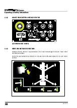
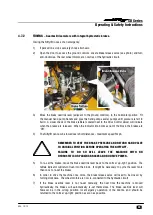
4.1.8
BATTERY MANAGEMENT: -
Battery condition is permanently monitored by the control circuit, such
that when available power has decreased to 20% of full charge, the battery status circuit begins to
"chop" the power to the hydraulic power packs. This function causes the drive system to alternately
stop and start, signalling to the operator that re-charging is necessary. At the same time the Klaxon will
begin to sound intermittently re-enforcing the charge warning. At this point, sufficient power remains to
drive to the nearest power point. Should the operator ignore the on-set of the discharge warning, the
"chopping" will continue until the machine is rendered inoperative. Immediate charging will then be
required.
Under no circumstances should a machine be left fully discharged or severe battery damage can occur
in a relatively short time.
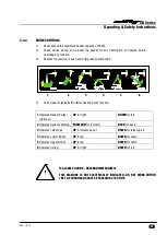
4.1.9
BATTERY ISOLATOR: -
A battery disconnect function is located beneath the centre bonnet section
which allows the machine control and power circuits to be isolated from the batteries themselves.
Under normal operation, the machine key switch should be used to isolate the machine, with the
Battery Isolators only being required for emergencies to disconnect the batteries in the event of a short
circuit. The battery charging circuit is connected directly to the battery side, so charging is unaffected
by use of this switch.
4.1.10
DUTY SELECTOR: -
On multiple power option machines, one of the functions on the Basket Control
Station will be a Duty Selector. This key switch allows the selection of either power option i.e. from
Diesel to Battery, or Gasoline to Battery, or vice versa. On other machines this same key switch serves
as an “ON-OFF” control.
4.1.11
DIESEL ENGINE:-
Generally a Kubota D722-E engine , described in the maintenance section of the
Workshop Manual, driving a twin bodied pump with direct mounted pump dump valves (one per
section). The arrangement allows two speed operation and fast throttle.
4.1.12
DIESEL BOX: -
Located inside the main electrical box, the Diesel relays combine all of the functions for
Dual power operation, (Bi-Energy machines), as well as controlling the Diesel engine itself. The relays
in this box control Starting, High Throttle, Pump Dump, Duty Selector and Diesel Stop Timer. There is
also an integral Thermal trip, which protects the Throttle solenoid and other functions.
4.1.13
GASOLINE ENGINE:-
Generally a Honda engine, described in the maintenance section of the Workshop
Manual, driving a single body pump with direct mounted pump dump valve. The engine is also
equipped with a throttle solenoid for two speed operation.
4.1.14
GASOLINE BOX:-
Located adjacent to the gasoline engine, the gasoline Box combines all of the
functions for dual power operation, as well as controlling the gasoline engine itself. The relays in this
box control Starting, High Throttle, Pump Dump, Duty Selector and Engine Stop. There is also an
integral Thermal trip, which protects the Throttle solenoid and other functions.
4.1.15
LPG OPERATION:-
On machines equipped for LPG operation (propane) the Honda engine will also have
an LPG vaporiser, valve lock and micro-vac switch. The supply and regulation of the propane is
governed by the installed gas bottle and regulator. The vapour take-off system requires a vaporiser to
convert the liquid gas into an airborne mixture. This is then held by the micro-vac switch and valve lock
until the engine turns over, creating a vacuum on the inlet to the engine carburettor. The micro-vac
switch then tells the valve lock to open, admitting the gas to the engine. If the engine is halted, the
system returns to normal, holding the gas until a re-start is attempted. When running on Gasoline, the