background image

2018.11 / m

2

Electric Power Generation

Installation and maintenance

LSA 40

Low Voltage Alternators - 4 pole

4455 en -

SAFETY MEASURES

Before using your machine for the first time, 

it is important to read the whole of this 

installation and maintenance manual.
All necessary operations and interventions 

on this machine must be performed by a 

qualified technician.
Our technical support service will be pleased 

to provide any additional information you 

may require.
The various operations described in this 

manual are accompanied by recom-

mendations or symbols to alert the user to 

potential risks of accidents. It is vital that 

you understand and take notice of the 

following warning symbols.

Warning symbol for an operation capable 

of damaging or destroying the machine 

or surrounding equipment.

Warning symbol for general danger to 

personnel. 

Warning symbol for electrical danger to 

personnel.

SAFETY INSTRUCTIONS

We wish to draw your attention to the 

following 2 safety measures which must be 

complied with:

a) During operation, do not allow anyone 

to stand in front of the air outlet guards, 

in case anything is ejected from them.

b) Do not allow children younger than 14 

to go near the air outlet guards.

A set of self-adhesive stickers depicting the 

various warning symbols is included with 

this maintenance manual. They should be 

positioned as shown in the drawing below 

once the machine has been fully installed.

WARNING
The alternators must not be put into 

service until the machines in which they 

are to be incorporated have been 

declared compliant with Directives EC 

and plus any other directives that may be 

applicable.

This manual is to be given to the end 

user.

The range of electric alternators and 

their derivatives, manufactured by us or 

on our behalf, comply with the technical 

requirements of the customs Union 

directives (EAC).

© - We reserve the right to modify the 

characteristics of this product at any time in 

order to incorporate the latest technological 

developments. The information contained 

in this document may therefore be changed 

without notice.
This document may not be reproduced in 

any form without prior authorisation.

All brands and models have been registered 

and patents applied for.

WARNING

This manual concerns the alternator which you have just purchased.

We wish to draw your attention to the contents of this maintenance manual. 

Summary of Contents for LEROY-SOMER LSA 40

Page 1: ...LSA 40 Low Voltage Alternators 4 pole Installation and maintenance Three phase 12 wire Dedicated single phase 4 wire ...

Page 2: ...guards in case anything is ejected from them b Do not allow children younger than 14 to go near the air outlet guards Aset of self adhesive stickers depicting the various warning symbols is included with this maintenance manual They should be positioned as shown in the drawing below once the machine has been fully installed WARNING The alternators must not be put into service until the machines in...

Page 3: ... 3 INSTALLATION 7 3 1 Assembly 7 3 2 Checks prior to first use 8 3 3 Terminal connection diagrams 8 3 4 Commissioning 11 3 5 Setting up 11 4 SERVICING MAINTENANCE 12 4 1 Safety measures 12 4 2 Routine maintenance 12 4 3 Bearings 13 4 4 Mechanical defects 13 4 5 Electrical faults 14 4 6 Dismantling reassembly 16 4 7 Table of characteristics 18 5 SPARE PARTS 20 5 1 First maintenance parts 20 5 2 Tec...

Page 4: ...transporter you may be able to claim on their insurance and after a visual check turn the machine by hand to detect any malfunction 1 3 Identification The alternator is identified by means of a nameplate fixed on the machine see drawing Make sure that the nameplate on the machine conforms to your order So that you can identify your alternator quickly and accurately we suggest you fill in its speci...

Page 5: ...teel frame End shields in cast iron Greasable ball bearings Mounting arrangement single bearing with standard feet and SAE flanges coupling discs two bearing with SAE flange and standard cylindrical shaft extension Drip proof machine self cooled Mechanical options Directpoweroutputby nonreconnectable cables regulatorfittedoutsidethealternator Protection against harsh environmentsh Air input filter...

Page 6: ... 12 wires T1 to T12 identification Exciter T7 T8 T9 T10 T11 T12 Armature MAIN FIELD R220 Aux windings Green Yellow Red Black T1 T2 T3 T4 T5 T6 Varistor Field STATOR 12 wires T1 to T 12 identification Voltage reference Exciter T7 T8 T9 T10 T11 T12 Armature MAIN FIELD D350 Power supply Detection 5 6 5 6 SHUNT three phase 12 wire AREP three phase 12 wire ...

Page 7: ...ng Before coupling check the compatibility between the alternator and the engine by performing undertaking a torsional analysis of the transmission alternators data are available on request checking the dimensions of the flywheel and its housing the flange coupling discs and offset WARNING When coupling the alternator to the prime mover do not use the fan to turn the alternator or rotor The holes ...

Page 8: ...nical checks Before starting the machine for the first time check that all fixing bolts are tight the length of bolt and the tightening torque are correct the cooling air is drawn in freely the protective grills and housing are cor rectly in place the standard direction of rotation is clock wise as seen from the drive end phase rotation in order 1 2 3 For anti clockwise rotation swap 2 and 3 the w...

Page 9: ...2 W T3 N L1 U L2 V L3 W NDE T9 T8 T7 T12 T10 T11 T4 T3 T2 T1 T5 T6 Winding 60 Hz 50 Hz 380 415 380 480 440 460 380 416 6 7 8 R220 voltage sensing 0 T8 110 V T11 D350 voltage sensing U T1 V T2 W T3 NDE N L1 U L2 V L3 W L1 U L2 V L3 W T9 T8 T7 T12 T10 T11 T4 T3 T2 T1 T5 T6 1 phase 1 phase or 3 phases FF Winding 60 Hz 50 Hz 220 240 220 240 220 240 200 250 260 6 7 8 R220 voltage sensing 0 T1 110 V T4 ...

Page 10: ... 60 Hz 50 Hz 220 240 220 240 250 260 200 220 240 6 7 8 R220 voltage sensing 0 T8 110 V T11 D350 voltage sensing V T2 W T3 M L L NDE T9 T8 T7 T12 T10 T11 T4 T3 T2 T1 T5 T6 1 phase or 3 phases L1 U L2 V L3 W L L Winding 60 Hz 50 Hz 110 120 120 110 120 120 130 6 7 8 R220 voltage sensing 0 T8 110 V T11 D350 voltage sensing U T1 V T2 W T3 NDE T9 T8 T7 T12 T10 T11 T4 T3 T2 T1 T5 T6 L L L3 W T1 T7 T10 T9...

Page 11: ... terminal box is connected to the electrical earth circuit The earth terminal is connected to the frame The connections inside the terminal box must never be subjected to stress due to cables connected by the user Diameter M6 M8 M10 M12 Torque 4 Nm 10 Nm 20 Nm 35 Nm Tolerance 15 3 4 Commissioning The machine can only be started up and used if the installation is in accordance with the regulations ...

Page 12: ...ous electrical connections in the installation Electrical servicing Commercially available volatile degreasing agents can be used Do not use trichlorethylene perchlo rethylene trichloroethaneoranyalkaline products These operations must be performed at a cleaningstation equippedwithavacuum system that collects and flushes out the products used The insulating components and the impregnation system a...

Page 13: ...led from the alternator or engine Alternator operating at too high a voltage 105 of Un on load Alternator overloaded Vibrations Too much vibration Misalignment coupling Defective mounting or play in coupling Rotor balancing fault Engine Alternator Excessive vibration and humming noise coming from the machine Phase imbalance Stator short circuit Abnormal noise Alternator damaged by a significant im...

Page 14: ...peed do not touch the AVR voltage pot P2 before running at the correct speed Voltage too high Adjust AVR volt age potentiometer Adjustment ineffective Faulty AVR Voltage oscilla tions Adjust AVR stabil ity potentiometer If no effect try normal fast recovery modes ST2 Check the speed possibility of cyclic irregularity Loose connections Faulty AVR Speed too low when on load or LAM set too high Volta...

Page 15: ...iode 12V battery Rh 50 300W ASSEMBLY A Field Assembly B Connect a Variac variable power supply and a diode bridge on both exciter field wires 5 and 6 Both these systems should have characteristics which are compatible with the field excitation power of the machine see the nameplate 3 Run the unit at its rated speed 4 Gradually increase the exciter field current by adjusting the rheostat or the var...

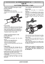
Page 16: ... torque See section 5 3 The bolts for fixing the feet on the housing and immobilising the stator must not be removed bolt of the stator lower Access to connections and the regulation system The terminals and AVR are accessed directly by removing the terminal box lid 41 Accessing checking and replacing the diode bridge Dismantling Remove the terminal box lid 41 Cut the fixing clamps of the exciter ...

Page 17: ... do not use an oil bath Check that both the preloading wavy washer 79 and new O ring seal have been fitted 349 on the NDE bracket 36 Replace the DE flange 30 and tighten the 8 fixing bolts Check that the whole alternator is correctly assembled and that all bolts are fully tightened Accessing the main field and stator Dismantling Follow the procedure for dismantling bearings Remove the coupling dis...

Page 18: ...t values consult the test report and are subject to change without prior warning Three phase 4 pole SHUNT excitation Resistances at 20 C Ω Type L N stator Rotor Field coil Armature VS1 0 66 3 12 5 1 40 VS2 0 48 3 3 12 5 1 40 S3 0 41 3 5 12 5 1 40 S4 0 35 3 8 12 5 1 40 M5 0 28 4 3 12 5 1 40 Field excitation current i exc A 400V 50 Hz i exc excitation current of the exciter field Type No load At rat...

Page 19: ...ces at 20 C Ω Type L N stator Rotor Field coil Armature VS1 0 3 3 12 5 1 4 VS2 0 22 3 3 12 5 1 4 S3 0 19 3 5 12 5 1 4 S4 0 16 3 8 12 5 1 4 M5 0 13 4 3 12 5 1 4 Field excitation current i exc A 230V 50 Hz i exc excitation current of the exciter field Type No load At rated load VS1 1 2 3 2 VS2 1 1 3 2 S3 1 1 3 2 S4 1 1 3 1 M5 1 1 3 For 60 Hz operation the resistance values are the same and the excit...

Page 20: ...echnical support service Our technical support service will be pleased to provide any additional information you may require For all spare parts orders or technical support requests send your request to service epg leroy somer com or your closest contact whom you will find at www lrsm co support indicating the comp lete type of machine its number and the information indicated on the nameplate Part...

Page 21: ...2018 11 m 21 Electric Power Generation Installation and maintenance LSA 40 Low Voltage Alternators 4 pole 4455 en 5 3 Exploded view parts list and tightening torque Single bearing AREP or SHUNT ...

Page 22: ...2018 11 m 22 Electric Power Generation Installation and maintenance LSA 40 Low Voltage Alternators 4 pole 4455 en Two bearing AREP or SHUNT ...

Page 23: ... DE flange 132 1 Cover option 33 1 Air outlet grill M5 4 133 1 Fastening bolt option M5 3 6 36 1 Non drive end NDE bracket 134 1 Support tab option 37 4 Tie rod M8 20 139 1 Wire shield tube option 40 1 Plastic cap 198 1 Voltage regulator AVR M5 6 41 2 Terminal box lid 322 1 Coupling disc 49 4 Cover bolt M5 3 6 323 6 Fixing bolts M10 66 53 1 Plug 324 1 Clamping washer 60 1 Drive end DE bearing 343 ...

Page 24: ... processes Our technical support depart ment can provide detailed directions on how to dismantle products on request Waste hazardous materials The following components and materials require special treatment and must be separated from the alternator before the recycling process electronic materials found in the terminal box including the automatic voltage regulator 198 current transformers 176 int...

Page 25: ...nufactured by Leroy Somer or on Leroy Somer s behalf comply with the following International Standards and Directive EN and IEC 60034 1 60034 5 and 60034 22 ISO 8528 3 Reciprocating internal combustion engine driven alternating current generating sets Part 3 Alternating current generators for generating sets Low Voltage Directive Nr 2014 35 UE dated 26 February 2014 Furthermore these generators de...

Page 26: ...2018 11 m 26 Electric Power Generation Installation and maintenance LSA 40 Low Voltage Alternators 4 pole 4455 en ...

Page 27: ...cient repair support and maintenance services Trust your alternator maintenance and support to electric power generation experts Our field personnel are 100 qualified and fully trained to operate in all environments and on all machine types We have a deep understanding of alternator operation providing the best value service to optimise your cost of ownership Where we can help Contact us Americas ...

Page 28: ...www emersonindustrial com 2018 11 m www leroy somer com epg 4455 en Linkedin com company Leroy Somer Twitter com Leroy_Somer_en Facebook com LeroySomer Nidec en YouTube com LeroySomerOfficiel ...

Reviews: