B R U S H L E S S D C M O T O R A N D G R E E N D R I V E
T M
M A N U A L
18
Nidec Motor Company
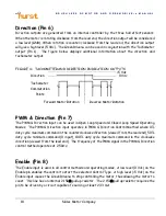
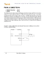
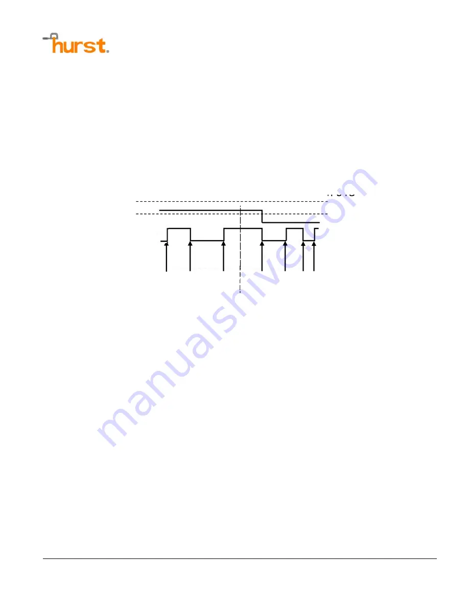
Direction (Pin 6)
Direction outputs are generated from an internal controller by the three hall effect sensors.
When the motor is rotating clockwise from the lead end, the direction output will be considered
a low level (GND). When rotation is counter-clockwise from the lead end, the direction output
will give a high level (5 Vdc). The GreenDrive
TM
can be used in conjunction with the Tachometer
output (Pin 1). The figure below displays additional information about the direction and
tachometer output.
FIGURE 4 – TACHOMETER AND DIRECTION INDICATION OUTPUTS
PWM & Direction (Pin 7)
The PWM & Direction input can be used in Open Loop Speed and Closed Loop Speed Operating
Modes. The PWM & Direction input operates in PWM & Direction Control Method where 0%
duty cycle maximum command in the counterclockwise direction (viewed from the lead end), 50%
duty cycle minimum command (0 input), 100% duty cycle maximum command in the clockwise
direction (viewed from the lead end). The frequency of the PWM signal in the PWM & Direction
control method operates at 2.5kHz.
Enable (Pin 8)
The Enable input is used in all control methods and operating modes. A low level (0 Vdc) on the
Enable pin enables the control to start the selected Control Type. A high level (+5 Vdc) on the
Enable input causes the GreenDrive
TM
to stop controlling the motor, thus allowing the motor to
coast. This line has an internal 2.15k
pull up resistor. The 2.15k
pull up resistor requires the
pin to be driven by a circuit capable of
sourcing at least 2.33 mA.
Commutation
Points
Direction
Tachometer
Forward Motor Rotation
Reverse Motor Rotation
+5 Vdc
0 Vdc


