B R U S H L E S S D C M O T O R A N D G R E E N D R I V E
T M
M A N U A L
17
Nidec Motor Company
Inputs/Outputs
Tachometer (Pin 1)
Tachometer outputs are generated from an internal controller by the three hall effect sensors.
On the standard Dynamo motor, the output is 15 pulses per revolution. The tachometer output
provides speed information. At each commutation point, the tachometer output changes state
independent of motor direction. The GreenDrive
TM
can be used in conjunction with the Direction
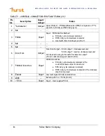
output (Pin 6). See Table 2 for additional information.
Externally Supplied Voltage Command Input
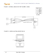
The user must supply a 0-4 Vdc input into Pin 2 on the control connector. If a 5 Vdc supply is to
be used, a 22 K
resistor must be placed in series with a 100 K
. potentiometer. If a 4 Vdc
supply is used, a resistor is not needed. The potentiometer consists of three pins, a supply
voltage input, a GND input and a variable command output. The user can adjust the command
output by adjusting the potentiometer with the wiper connected to the command input and the
other two potentiometer connections attached to the control connector Pin 10 and control
connector Pin 9 pins.
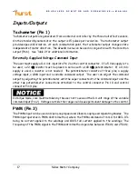
In torque mode, care must be taken by the user not to exceed the 0-4 volt range of the variable
command input (Pin 2). Voltages outside this range could cause permanent damage to the control.
PWM (Pin 3)
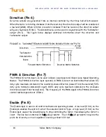
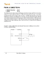
The PWM input can be used in Open Loop Speed and Closed Loop Speed Operating Modes. The
PWM input operates in PWM Control method, where the PWM command is from 0 to 100%; 0%
being no current applied to the windings and 100% full current applied to the windings. The
frequency of the PWM signal in the PWM control method operates between 15 kHz and 25 kHz.

